


Hi Ti, I'm testing LDC1612 and now I found a problem, when the target is in steady state, the output data of LDC1612 is not a straight line. I want to know why and how to improve my design.Help me please~~~
L:Ferrite Magnetic Can(shield)+ PCB coil
C:1000pF /np0/1%
target : 90mm*90mm steel
distance:1~3mm
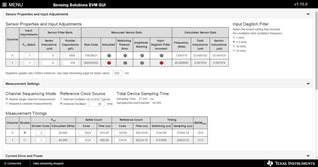 config @1mm
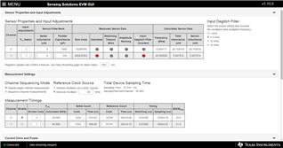 config @3mm
 Idrive settings
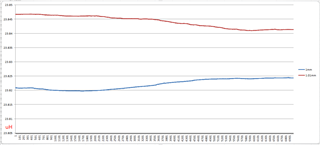
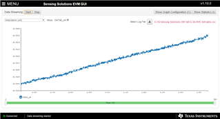 The target has been stationary, why is the data still rising?
 Action 10μm, sampling 7000 data
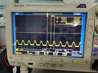 @1mm the LC
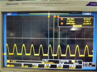 @3mm the LC
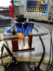 my test device
