This thread has been locked.

If you have a related question, please click the "Ask a related question" button in the top right corner. The newly created question will be automatically linked to this question.

IVC102: Design considerations with IVC102 & PH

Part Number: IVC102
Other Parts Discussed in Thread: DDC264

Hi Team,

We would like to ask your help regarding our customer's inquiry below.

My team and I are currently working on the hardware design of a handheld luminometer. For the measurement process we found out that the best solution for the current levels that we will be measuring is the IVC102 with a S1227-66BR Photodiode. On our project concept stage the following circuit was considered and tested:

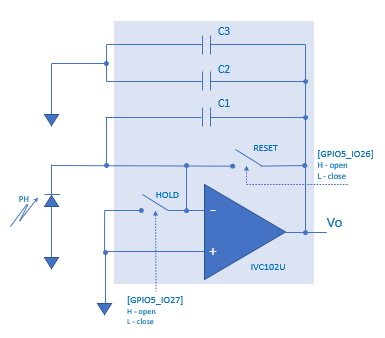
In order to compensate the S1227-66BR’s dark current and subtract it from the measurement, it was proposed to actually measure this current with the use of a shutter device before and after each measurement cycle.

Recently I came across a Medical Applications Guide from 2007 produced by TI (https://www.mouser.com/catalog/specsheets/tismedicalappsguide.pdf) where a different circuit using two IVC102 is proposed claiming common mode errors are subtracted.


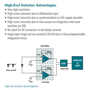
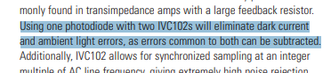
From a theoretical stand point, I can see that the circuit will actually mitigate the Dark Current, but I would like to ask if the requirement of a Shutter device on my previous circuit can be ignored with this improved configuration. Furthermore, I would like to know if I should have some additional considerations to the paired IVC102 of the improved circuit. Should the ICs be from the same batch/bin? Should we test the devices be tested in some way to prevent excessive parameter dispersion? How would it affect?

Additionally, checking the datasheet I see that a carefully selected, low noise power supply should be used for this IC, as with any analog measuring device. In that regard, I would appreciate if you could assess a proper supply from TI’s catalog for this application (handheld device, input voltage +5 V).

Finally, is there a pre-selected Analog to Digital Converter with I2C interface that is recommended for this circuit?

Regards,

Danilo

  • Hi Danilo,

    I chew on this and I am not sure there is any other way to remove the dark current of the photodiode than the shutter approach you describe. I.e., one has to measure the current from the PD with no signal (illumination).

    One could disconnect the PD but then you would be measuring just leakage currents at the input of the IVC, not the dark current of the PD.

    The circuit you show is good for common mode errors, like say, coupling on the trace from PD to IVC, inducing a current on that trace. Mirroring that on the other side of the PD and assuming coupling is very similar on that trace, then sure, you could subtract it. It could also remove input leakage current from the IVC assuming that they are somehow match, which I don't know (sorry no answer on that to your question). But regardless the shutter would also help remove these without the need for a second IVC.

    Regardless, all that has nothing to do with dark current or ambient light, as the text seems to say. The author may be meaning to have a second PD "identical" to the first but that does not see the signal, only the ambient. But that is not what the diagram shows. I don't know, maybe I am missing something...

    On the power supply, let's see if someone else can jump into this thread. It is not my area of expertise. I checked the DDC264 EVM which has a 5V supply and we seem to use the REG1117-5. On the ADC, same, not an expert on TI portfolio. What sample rate/resolution are you looking for?

    Regards,
    Edu

  • Hi Edu,

    Thank you for your response. Please see the feedback of our customer below.

    Thank you for your answers. I see that my current approach should be ok for my application.

    About the Power Supply, I think the REG1117-5 (5 V output?) is not enough to power the IVC102 since the chip also requires negative supply. But I understand from your answer that a simple SMPS supply will not suffice and I need proper voltage regulation with LDOs. Am I correct?

    About the ADC, the circuit one of my colleages tried had a MCP3425 but I saw that I need to measure negative voltages (around -60 mV) which the MCP might not be the best choice for. A 16 bit, 15 SPS chip should be suitable for my application.

    Regards,

    Danilo

  • Danilo,

    On the supply and ADC, please contact someone on the appropriate team or in SEM. But certainly a switched power supply will very likely not work for them. (There are some tricks, synchronizing stuff, filtering, etc... but very hard to make it work if ever).

    Regards,
    Edu