This thread has been locked.

If you have a related question, please click the "Ask a related question" button in the top right corner. The newly created question will be automatically linked to this question.

TUSS4440: TUSS4440: ZC_CMP_STG_SEL CONFIGURE

Part Number: TUSS4440

Hi team,

My customer need assistance:

Question Details:

Set register ZC_CONFIG:0XB1

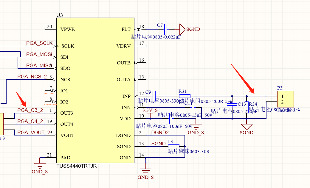
Schematic as follows, test point: connector P3-pin1, IC U3-pin1

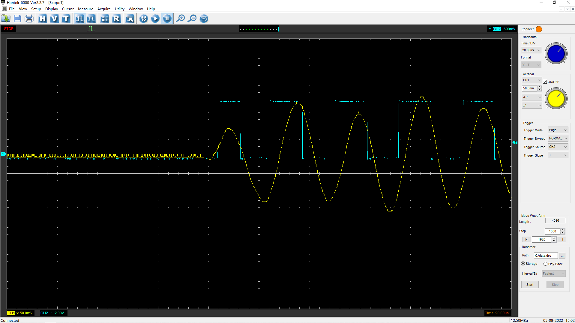
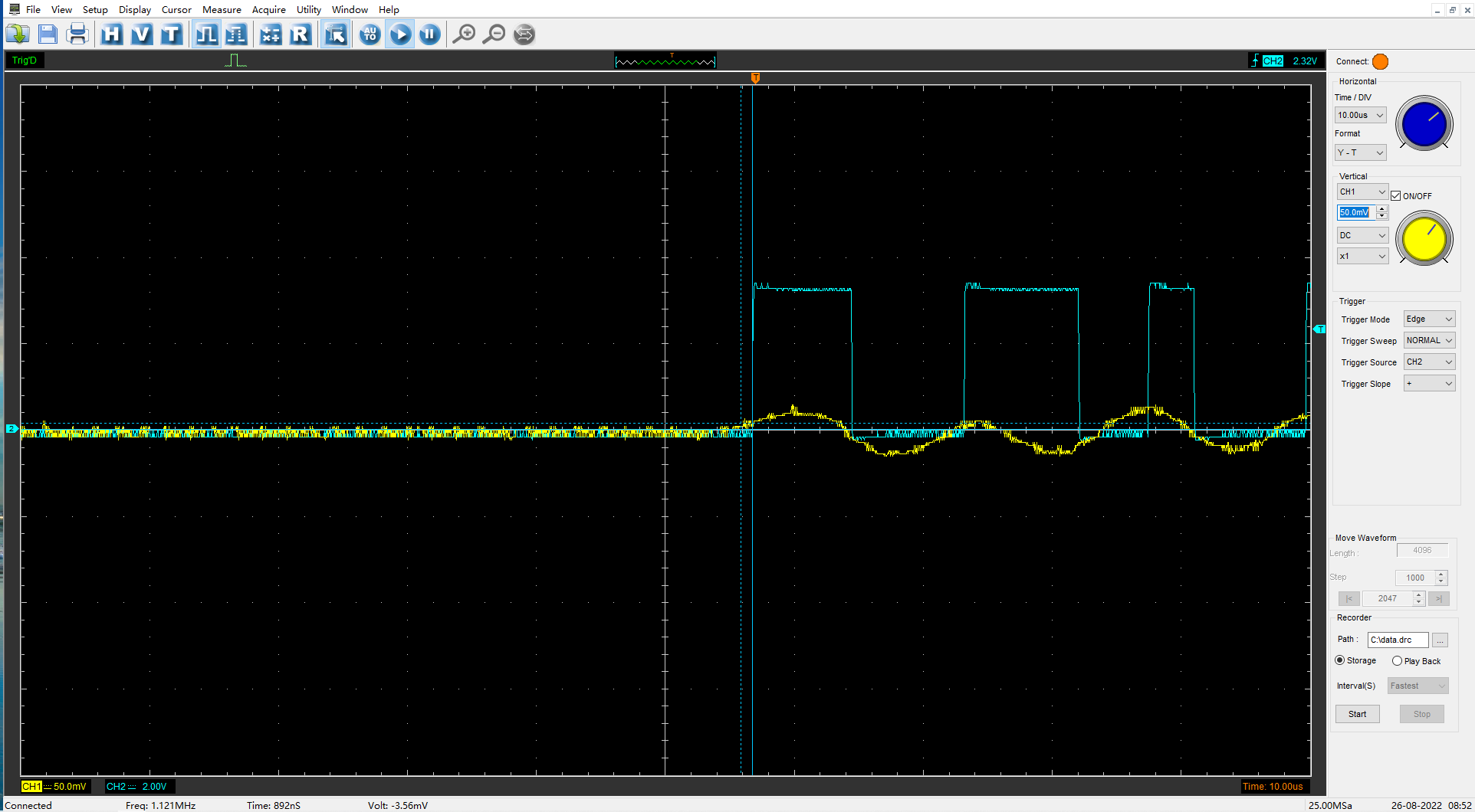
  • Waveform as follows:(yellow--P3-pin1,green--U3-pin1)

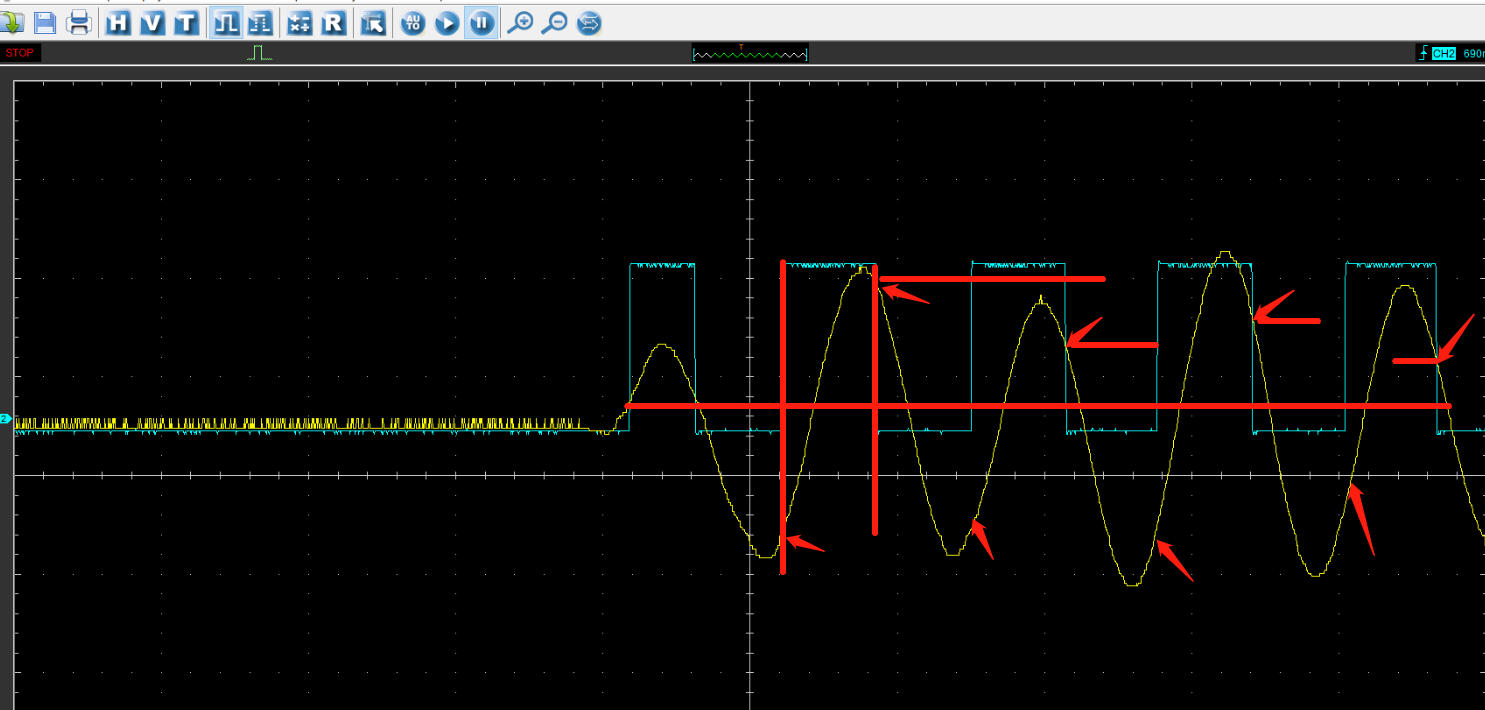
We can see within the first cycle ZC output OUT3 action normal, low-->high when signal higher than threshold value and high-->low when lower than this value; but the logic is not correct in the following cycles, please help to check why?

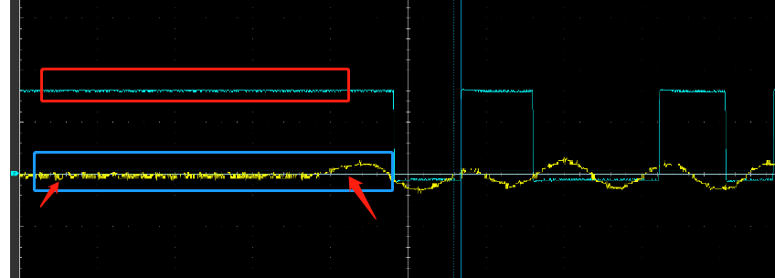
  • Almost the same input signal, the OUT3 action is different:

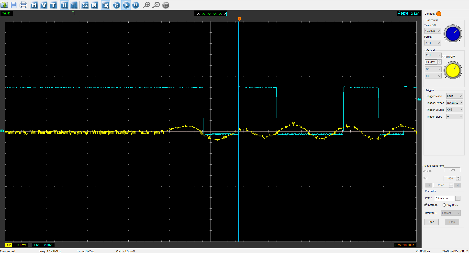
In the follow pictures, original signal--yellow, OUT3 output--green,

We can see in the second picture OUT3 not changed when the signal became higher whthin the first cycle while different action in the first picture,

Need to check why this happened?

Kindly check and help. Thanks.

  • Hi Chong,

    One of our ultrasonic experts is out today. He should be able to respond when he is back tomorrow.

    Regards,

    Mekre

  • Hello Chong,

    Thanks for posting to the sensing forum! Just a couple of questions first, were the same register settings for the zero cross comparator (ZC_CONFIG:0XB1) used for all these scope captures? Do you know what the scale is for the yellow signal on the first image?

    Best,

    Isaac

  • Hi Issac,

    I got the reply from the customer:

    Register settings are the same. Actually this is the signal measured through the same channel.
    The scale is 50mV, just like on the other images. I attach the original image.

  • Hello Chong,

    Thanks for the information. I am only able to replicate a similar behavior when I have an extremely low amplitude sinusoidal signal and if I have the comparator threshold set high for the signals amplitude. This means that the signal is not strong enough to trigger the threshold to pull up or to pull down. So in the customers image there may have been noise in the circuit that caused the comparator to trip the signal up high but there was not enough noise to cause it to go low until the sinusoidal waveform was presented.

    Best,

    Isaac

  • Hi Issac,

    I got the reply from the customer:

    Let me say my understanding, and you can confirm whether it is right:

    1. In the figure below, the ZC output is always at high level before the arrival of the positive Xuan wave because the voltage caused by the original signal noise is not low enough. Does the ZC output maintain the previous state? Until the ZC output low level is triggered in the falling cycle after the positive dark wave comes? From the diagram, the trigger point is indeed lower than the normal voltage, but my setting is 0xb1, and the comparison voltage of the reverse output cannot be lower than 0V, right? Is there a delay

    2. This problem is not explained. Why are the positive and negative trigger points of ZC output not the same voltage point?

  • Hello Chong,

    That is correct the ZC comparator latches the last known state. So if the last known state was a signal that caused the comparator to latch high then it will stay high until a signal is strong enough to pull the signal low. The voltage difference is provided by the hysteresis in the comparator, the comparator will use the programmed hysteresis in which it will change to a high voltage as well as a different voltage to when it will change low.

    I think the voltage points change because the input being used for the ZC comparator, the selection is INP-INN, have you tried monitoring the INN signal to see what they look like in your system? This might give you a better idea as to why the comparator is switching the way it is. Is customer directly feeding a sinusoidal signal to the input here or is this an actual return from a transducer?

    Best,

    Isaac