This thread has been locked.
If you have a related question, please click the "Ask a related question" button in the top right corner. The newly created question will be automatically linked to this question.
Hi team,
Here's an issue from the customer may need your help:
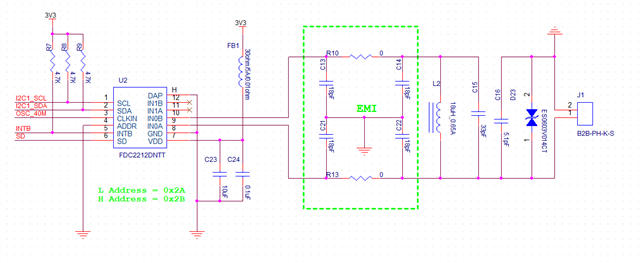
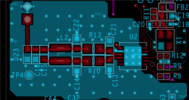
Signals captured in the 80 to 200 MHz band are subject to interference and cannot be used. According to the demo board manual, two capacitors close to the chip pins can be adjusted for interference immunity:
1) Is it required to adjust the values of the 4 capacitors together when adjusting the capacitors?
2) Regarding the above frequency band, is it required to be adjusted up or down from the original 18 pF? And are there recommended values?
Could you help check this case? Thanks.
Best Regards,
Cherry
Cherry,
What is the sensor frequency?
Are they using our EVM, or their own PCB?
Just so you know, we are recommending the FDC1004 over the FDC2xxx.
The FDC1004 supports active shields, which helps manage EMI.
The FDC2xxx family does not have this feature, which causes additional EMI challenges in many applications.
regards,
John
Hello John,
Thanks for your support.
What is the sensor frequency?
Sensor frequency is 6.5MHz, external clock is 40MHz.
Are they using our EVM, or their own PCB?
They are using their own PCB.
Thanks and regards,
Cherry
Cherry,
Thank you for the additional information.
Can the customer provide a schematic and layout of their PCB, along with pictures or diagrams of any additional shielding they are using?
As you might already know, the E2E will be down from Sept. 28 to Oct. 2, so this thread will be on hold during this time.
Regards,
John
Hi John,
The remaining layers corresponding to the PCB are all GND.
Thanks,
Annie
Annie,
Thank you for the layout and schematic.
I have an idea that might help, but it will take a day or two before I can report any results.
As you might know the E2E will go off-line later today.
I will close this thread for now, and we can communicate over email from here on.
regards,
John
Apologies Annie.
I will email Cherry with the updates and she can pass them on to you.
John
Hi John,
May I know is there any feedback from your side since I haven't got your email?
Thanks and regards,
Cherry
Apologies Cherry.
I did not follow through with an email as I promised.
Would you prefer to continue on this thread or switch to private E2E messages?
Regards,
John
Hi John,
Would you like to continue on this thread since we could point the end customer to our discussion?
Thanks and regards,
Cherry
Cherry,
As mentioned earlier in the thread, many of our customers have struggled to get to production with the FDC2xxx devices because of their sensitivity to EMI and a lack of options for shielding.
For this reason, we recommend using the FDC1004 which has active shields and also has a non-resonant switch-cap front end.
The best option - other than increased shielding - is to reduce your sensor frequency so frequencies above that are attenuated more.
Some simulations of your sensor circuit are summarized in the plot below as an example.
The blue curve shows the results of an AC sim of the circuit from your schematic.
The simulation shows a resonant frequency of about 5MHz, which is a little lower than you mentioned, but will serve as a point of comparison.
The orange curve results from increasing C15 from 33pF to 135pF. This causes the resonant frequency to decrease from 5MHz to about 3MHz.
The thing to notice is the level at 8MHz and above decreases 11dB, which would reduce EMI in the range of 8MHz - 200MHz by at least that amount.
You can also accomplish this by increasing the values of C13, C14, C21, C22 to 120pF (ΔC = 102pF).
Reducing the sensor frequency further would get you more EMI attenuation.
The TINA-TI schematic of your circuit is attached.
Please let me know if you have any questions.
Regards,
John