This thread has been locked.

If you have a related question, please click the "Ask a related question" button in the top right corner. The newly created question will be automatically linked to this question.

Strain Gauge on torsion rod reversed voltage change direction

Other Parts Discussed in Thread: INA826

Hello ,

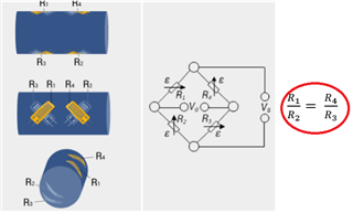
I am having 4 strain gauges in a wheatstone's bridge configuration installed in 45 degrees configuration shown on the photo below on torsion rod.

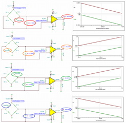
I am using an instrumentation amplifier with high gain in order to amplify the signal. The voltage signal actually changes correctly with the applied torsion. However , after implementing the same setup on multiple torsion rods , I am getting a reversed voltage change although I am applying the force in the same direction and using the same weight and all the strain gauges are installed in the same directions. By reversed voltage change , I mean that the voltage is increasing on one setup while increasing force on a specific direction and the voltage is decreasing on the second setup while increasing the force in the same direction.

Here are photos for the 2 setups that are behaving oppositely.

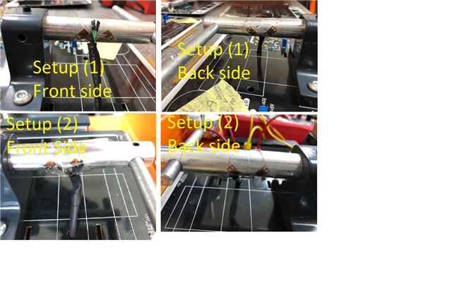
I can't find any differences between the 2 setups. I need help from someone who is expert in strain gauges. Note that when I apply force on the other direction of the axe of setup number 1 , it increases. but on the same side like setup number 2 it behaves oppositely.

Thank you very much in advance.

BR

Amr Wael

  • Hi Amr, 

    Let me provide you 4 examples to explain your issues. Please pay attention to the location of Rsg (stain-gauge) in the simulation. 

    Assume that the excitation voltage reference is 3.300Vdc and a nominal unstressed strain gauge has a resistance of 1kΩ. Dual voltage supply rails are used in INA826. 

    INA826 Multiple Strain Gauges 12012022.TSC

    From the simulation, you will notice that Rsg1 and Rsg4 will have the same Vout responses and Rsg2 and Rsg3 have the identical responses, if all strain gauges are kept identical.  

    If one stain gauge is being monitored per Wheatstone bridge circuit, it is easier to know which sensor is being measured in tensile vs compression stress.  

    If two strain gauges are being monitored per Wheatstone bridge circuit, the algorithm is still fairly simple to identify. 

    If all four stain gauges are being monitored and changed at the same time in a circuit per given operation,  the computation algorithm will be fairly complex. It is doable, but you have to know the system very well, and you need to have a software algorithm to identify the peaks and/or valleys of the stressed behaviors. 

    My suggestions are that you need to obtain two different impedance types of strain gauge sensors, where you will keep the same ratios as shown below. This way, you may be able to differentiate Vout signals from the stressful conditions.  

    With all 4 strain gauges mounted on the same rotational shaft under a single instrumentation amplifier (IA) circuit, it is likely that you need to know the system's behaviors very well. You may have to characterize each stain gauge individually and combine the overall voltage and behaviors. The computation algorithm may require to deconvolute the output signals in order to identify the stressed components. 

     We have a very wide instrumentation amplifier selection as shown in the link below. If you need further assistant, please let me know. 

    https://www.ti.com/amplifier-circuit/instrumentation/overview.html?keyMatch=INSTRUMENTATION%20AMPLIFIER

    Best,

    Raymond

  • Hi Amr, 

    I have not hear from you since last reply. I hope that your issues are being resolved.  

    I am going to close this inquiry. If you have additional questions, please let us know. 

    Best,

    Raymond