This thread has been locked.

If you have a related question, please click the "Ask a related question" button in the top right corner. The newly created question will be automatically linked to this question.

DRV5055-5057EVM: Inquiry

Part Number: DRV5055-5057EVM
Other Parts Discussed in Thread: DRV5056, , DRV5057, DRV5055

Hi,

Good Day.

I thought the DRV5056 linear hall sensor should be a suitable starting point and bought the EVM for the same.

I would like to know that If I connect with the USB cable how will I know the power supply range?

I would also like to know more about the DRV5055-5057EVM. Is there any tutorial for the same? Like how it works other than the user guide. Also, I read in the datasheet that the sensor can function in either 3.3V as input or a 5.5V input supply.

Please advise. Thank you very much.

Best Regards,

Ray Vincent

  • Ray,

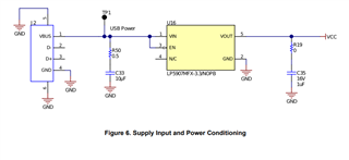
    Typical USB connections will provide 5V.  The 5V from the USB is converted to 3.3 on the DRV5055-5057EVM and this is used as VCC for the rest of the PCB

    The acceptable input range for this LDO is 2.2V to 5.5V, but as it is an LDO, it is important to ensure that this voltage is above the dropout voltage (worst case is 250 mV).  Since we are driving 3.3V on the output, I wouldn't try to operate this EVM with a supply below 3.6 V.

    This particular EVM is configured with A1-A4 sensitivities of each device: DRV5055. DRV5056, and DRV5057.  The EVM is set to use the push button to select which device is being sampled, and then the output is either displayed in terms of the actual voltage, % FSR, or calculated input of mT.  

    DRV5055 and DRV5056 are sampled directly by the onboard MSP430, but DRV5057 must be selected through a multiplexer before being routed to the MSP430.  

    The device may operate at 3.3V and 5V supplies.  The sensitivity of the device is ratiometric, meaning that it will vary with respect to Vcc.  This is helpful when the ADC reference voltage is the same, as it reduces measurement uncertainty that may occur as Vcc varies.