This thread has been locked.

If you have a related question, please click the "Ask a related question" button in the top right corner. The newly created question will be automatically linked to this question.

HDC2080: Understanding Threshold Interrupt Behaviour

Part Number: HDC2080

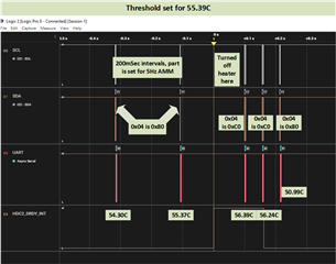
The HDC2080 manual (pages 11 to 14) describe the behaviour of threshold crossing interrupts depending on the mode and polarity that is set.

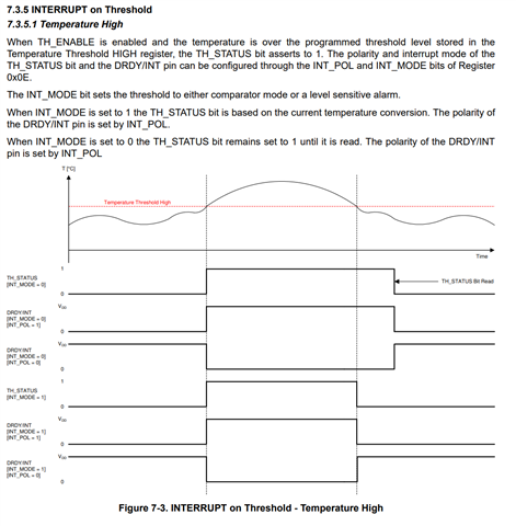
On page 11, dealing with the Temperature High crossing threshold, in mode 1, comparator mode, with polarity set as 1, 2 interrupts are driven, 1  rising edge interrupt when the temperature exceeds the threshold and 1 falling edge interrupt when it drops back down again below the threshold.  When the first interrupt occurs the value of TH_STATUS is 1.  When the second interrupt occurs it presumably should be 0 but my interrupt service routine code as follows still has it as 1. 

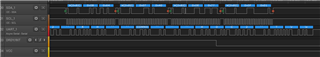
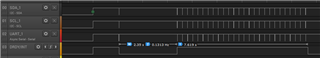
The sensor is set to automatically acquire temperature and humidity every 10 seconds

The Data Ready interrupt is disabled. All threshold interrupts are enabled. The DRDY/INT pin is set to interrupt on rising or falling edge.

Sensor is heated just past the temperature threshold then allowed to cool.

What am I doing wrong? Thanks.

Interrupt Service Routine

uint8_t intStatus = HDC2080_readInterruptStatus( ); // This reads HDC20880 register 0x04
intStatus = (intStatus >> 3) & 0x0F; // Shift bits to start of byte
humidityViolation = (intStatus && 0x03); // high or low violation
temperatureViolation = (intStatus && 0x0C); // high or low violation
if ((temperatureViolation == true) || (humidityViolation == true)) { // Threshold violation
  Do stuff here when the rising edge interrupt occurs when temperature crosses the threshold
  However, this gets executed on the 2nd interrupt as well as the 1st
else { // Within threshold
  Do other stuff here when the falling edge interrupt occurs, when the temperature drops below the threshold
  However, this never gets executed
}
  • Dear Ron - 

    Thanks for the post and welcome to E2E!

    Here it may help if you put a logic analyzer on your I2C bus and then share that capture, if possible, if you are still having issues after reading below.  

    Here is an example I did for this kind of usage, where in the setup code which runs after POR or SR, the configuration of registers 0x0B (with a 0x64, for 24.45°C), 0x07 (with a 0x40, TH_ENABLE bit set), 0x0E (with a 0x77, 5Hz, DRDY/INT enabled, INT_POL = Active high and INT_MODE = comparator mode) is done, then the firmware starts a conversion (0x01 to register 0x0F)

    (click on image to enlarge)

    Then, in this specific example, about 2.35 seconds later, the interrupt fires because I raised the temp above the threshold, and I read register 0x04 (where I get a 0x0C) and begin reading at the 5Hz rate, until the part cools back down and the interrupt is no longer active. 

    Zoom in on the first readout after IRQ, temp is circled in red, i put it out second on my UART in this example

    Here is the full capture, you can get the viewer software from Saleae (this is the older version) 

    https://support.saleae.com/logic-software/legacy-software/older-software-releases#logic-1-x-download-links 

    HDC2_High_Temp_Threshold_Interrupt_Usage.logicdata

  • Hi Josh, thanks for your reply.

    Probably didn't explain the problem well enough.  The issue is not whether interrupts are happening, we are getting an interrupt on rising and falling edges of the DRDY/INT pulse, but the value of the status bits in register 0x04 after the temperature has dropped when the second interrupt occurs.  After the first interrupt with temperature having crossed the threshold the shifted value of 0x04 is 0x08, which is as expected with TH_STATUS set high, however on the second interrupt when the sensor has cooled below threshold the value of 0x04 is still 0x08, when from my reading of the manual it should be 0x00, or have I misunderstood how it works? Thanks. Ron

  • Ron - 

    Maybe if you could capture what you see with a logic analyzer, that would be best, from power up if possible, so i can see how you are setting the part up and possibly then recreate/explain whatever is the case. 

  • Hi Josh,

    Yeah, unfortunately I can't easily get a probe onto the pin as this is about upgrading firmware on one of our existing boards.  Instead I have an led that flashes differently on different branches of the conditional and am also reading the value of 0x04 after interrupts.  From this it is clear that the first branch of the conditional is executing after heat is applied to the sensor, then again as the sensor is allowed to cool.  In both cases TH_STATUS is being set to 0x08 (which is correct being right shifted by 3 bits), whereas I was expecting it to be cleared when the sensor cools below threshold.  So what I'm really after is just confirmation that the sensor really does clear the TH_STATUS bit exactly when temperature falls back below the threshold, coinciding with the falling edge of the DRDY/INT threshold pulse (data ready interrupt is off).

    Actually though I realise now that if the TH_STATUS bit is cleared when the temperature drops below threshold it won't help anyway to detect that event as after TH_STATUS bit is set high after increasing temperature violates the threshold, it will be cleared just by reading the register. So in that case I need to look at whether the interrupt is rising or falling, e.g. 

    bool isRising = HAL_GPIO_ReadPin(DRDY_INT_PORT, DRDY_INT_PIN) ? true : false;
    Which appears to solve the problem. Does that make sense?
  • Ron - 

    If it makes sense to you, then great! Here you could also compare your expectations and adjust as required to the polarity, trigger and different release behaviors of the pin, which are based the settings you prefer or action you wish to take (i.e. reading 0x04).

    https://www.ti.com/lit/ds/symlink/hdc2010.pdf (page 11, for Temp High example usage, following pages show others)

    In this case, using Mode 0 would result in the IRQ not going low until it is serviced by a read. In Mode 1, the pin changes state on the crossing of the threshold.   

  • Ron,

    To add to what Josh said, the behavior of the interrupt is based on the INT_MODE and INT_POL configuration.  Figure 7-3 shows the behavior for high temp and figure 7-4 shows low temp based on INT_MODE and INT_POL.  


  • Hi Eddie

    The manual from my reading of the diagrams above, indicates that for temperature high, when the temperature falls below the threshold, in comparator mode, (with poll set to 1, data ready interrupt off, threshold interrupt on), DRDY/INT pulse returns low, then TH_STATUS should be unset, whereas from my observations, contrary to the manual it is set.

    This was investigated by the threshold interrupt service routine (configured to fire on both a rising and falling edge) being coded to indicate the level of DRDY/INT (as above) whilst also saving the value of TH_STATUS so that it can be reviewed later.   In that case when DRDY/INT goes low and TH_STATUS is read and stored, its value is shown to be set high (the variable 3 >> value is 8).  Hence my original query about understanding as the manual appears to be incorrect in that regard.

    To check this with a logic analyser the value of TH_STATUS would need to be determined when DRDY/INT goes low.

    Of course its possible that I've made a mistake, hence the original question, which surely needs this check to prove that the behaviour of the sensor is as indicated in the manual. Thanks.  Ron.

  • Hi Ron,

    I understand your question.  Tomorrow, I will get a logic analyzer on the EVM and duplicate your configuration, but also monitor DRDY/INT.  I will let you know what i find.  

  • Ron,

    Please see my captures below.  The high temp threshold is set to 28.32C.  After this threshold is crossed exceeding the threshold, DRDY is asserted, and register 0x41 reads 0xC0 indicating an interrupt.  When the temperature is then crossed to be below the threshold, DRDY is no longer asserted and register 0x41 reads 0x80, indicating no interrupt and conversion complete.  I have included the shots below, but also attached the full capture if you would like to check this too.  You will need the Saleae logic analyzer software to view.

    After DRDY goes high indicating threshold exceeded:

    After DRDY goes low indicating that threshold no longer exceeded:

    If you could provide some logic analyzer shots of what you are seeing, that would be helpful as the behavior I have seen follows the datasheet.

  • Thanks Eddie, thanks for undertaking that test.

    As mentioned before, I can't easily get logic probes onto the HDC2080 pins of the custom board available here, not without potentially damaging the board. Consequently my tests were as described above. Hence the uncertainty.

    One question though before marking this as resolved. In your second logic analyser capture did you read the register only after the temperature dropped down below the threshold, otherwise reading the register when the threshold was initially violated would itself have cleared the register bits?

    Actually given this latter point, status bits being cleared when the register is read, the threshold status crossing registers are only useful to identify which type of threshold has initially be violated, but not then when it drops back to within a threshold boundary, partly determined by reading the voltage level of the DRDY/PIN, or otherwise determining that an interrupt is a falling one. If the threshold for both temperature and humidity had been crossed then it would be necessary to compare their actual values with the threshold to determine which one or perhaps both had crossed back again.

  • Ron - 

    Eddie and I are working on an example for you, (which is using the heater feature in the device) to show the behavior in real time easily. 

    The basic loop is from power up, we configure the part, turn on the heater and run it to threshold, then turn off the heater and keep reading.

    the second read while DRDY/INT is still high occurs before the drop. 

    Here is what it looks like so far - more on Monday!

    (click on images to enlarge)


  • What a great idea for temperature testing Josh, better than a hot air gun!

    We've avoided using the heater in our battery operated commercial fridge/freezer wireless product due to its large current draw, but it could be very useful for self testing via over the air command. 

    What's unclear to me is how 0x04 is being read without clearing the flag bits? The manual indicates that a read itself clears those bits.

  • Ron - 

    Thanks - that read was me playing around with the firmware, I was looking at switching to one shots during the pin being high. Here is a little cleaner version, where I left it in AM mode - you can see after reading the value, i turn off the heater (keep in AM mode) and then the IRQ drops. 

    From reset

    Zoom in on IRQ - here i do a read because of the IRQ, then turn the heater off

    The interrupt mode determines when the pin changes state, whereby int_mode =0, the pin changes state on being serviced, in mode 1, the pin changes state based on temp.

    I think we will make an E2E FAQ for this, because this is a lot of detail we can expand more on - thanks for bringing it up.  

  • Thanks again Josh.

    It is a brilliant sensor device, certainly worth writing a FAQ.  Our wireless product is now operating in sleep mode, capturing temperature / humidity in AM once per ten seconds, using < 5 uA average. When the temperature goes over threshold the device wakes up (rising interrupt), reads the 0x04 register for over temperature, sets an over temperature threshold timer then goes back to sleep, if there is a DRDY/INT falling interrupt before the over temperature threshold timer times out it cancels the alarm, this latter is detected by reading the voltage level of the DRDY/INT pin, which in comparator mode of course goes low immediately the temperature has dropped back below threshold.  If the over temperature threshold timer times out an over temperature alarm is sent wirelessly. This timer is to reduce false alarms when a fridge/freezer door is opened during normal operations when the temperature can briefly go over threshold.

    Though for some reason I still can't clearly get into my head around what should be happening with the threshold status bits as opposed to the DRDY/INT pin voltage.

    Here's my take:

    In int_mode = 1 after the DRDY/INT pin goes high due to an over temperature threshold violation,  if the 0x04 register is read it will show TH_STATUS bit as set.  However reading the register should, according to the manual, itself cause it to be cleared. Consequently when the temperature drops below threshold the DRDY/INT pin voltage will go low but the TH_STATUS bit value will not change as it is already cleared from the previous read.  However if the 0x04 register is not read after the rising interrupt, TH_STATUS will be cleared automatically upon a falling interrupt when DRDY/INT pin voltage drops low.  Is that a correct description of behaviour when int_mode = 1 or have I misunderstood?

  • Hi Ron,

    I took some more captures to produce what you are describing.  Temperature high threshold is set to 60C.  On power up, the heater is turned on and will remain on until the DRDY pin is triggered at 60C.  At this point, the heater is turned off and a 6 second delay occurs allowing the sensor time to cool down.  No read of register 0x04 has occurred after the DRDY interrupt.  After the 6 second delay, the sensor is well below the 60C threshold(its about 37C after 6s) and register 0x04 is read.  I am reading a 0xC0 indicating the TH_STATUS bit was not cleared. 

    I also understand the datasheet to indicate that mode 1 should follow the current temp conversion, therefore would also follow the DRDY pin.  I am checking internally on this and we may need to update the documentation if necessary.

    Zoomed out capture showing DRDY interrupt, delay, then 0x04 read.


    Read of 0x04 after temperature is below threshold

  • Hi Eddie, thanks for doing that experiment, which does sound like I'm not going entirely senile after all!

    Concur with your reading of the documentation that TH_STATUS should be cleared due to a falling level interrupt when int_mode = 1, +ve polarity.

    If there was ever a new version of the sensor it would be useful if the behaviour was as in the manual except the 0x04 register isn't cleared when it is read. Rather its cleared by a specific command. That would enable the particular sensor event associated with an interrupt (one of the four possible combinations) to be determined.  Otherwise if humidity and temperature have both violated a threshold you would have to do a temperature and humidity comparison to be sure which one an interrupt was for.

    Thanks again to yourself and Josh for persisting with this and doing the experimentation.

    Will mark your above response as resolved.