This thread has been locked.
If you have a related question, please click the "Ask a related question" button in the top right corner. The newly created question will be automatically linked to this question.
Hi Experts,
This is a continuation of the previous e2e thread: AWR1843BOOST: How to get data generated to plot ISAR images by AWR1843.
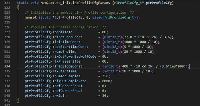
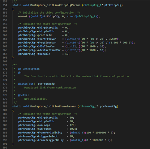
I am passing the screenshots of ptrProfileCfg, ptrChirpCfg, ptrFrameCfg from mss.c
I am having difficulty in taking values, because of notations like 1U<<26.
How to get the values of "fc, Fs, sweepSlope, Tc, max_value" from these.
Please help to share the code that you have used.
Thank you in advance for your support.
Best regards,
Jonathan
Hi Johnathan,
Please refer to the file mmwave_sdk_<ver>\packages\ti\control\mmwavelink\include\rl_sensor.h
This will have the comments on how to calculate/set values of a given parameter to the device.
Regards,
Kaushik
Hi Kaushik,
Thank you.
Not sure as to what max_value it is you are referring to. Please give more details.
And the max_value is the value used for normalization which is used in 'get_params.m' file of github code I previously referred to.
We are looking forward to your update.
Best regards,
Jonathan
Hi Johnathan,
As Cesar pointed out in the previous thread, we don't provide support regarding the github code you referred to. You would have to contact the developer of the code or go through it yourself and arrive at an understanding.
Regards,
Kaushik
Hi Kaushik,
Please help us once again.
The customer is asking us to give the values of the required parameters from the screenshots as they are unable to calculate the values.
They reminded us about the problem and issue that was raised originally on how to get the Range-Doppler Heatmap from the data.
Best regards,
Jonathan
Hey Johnathan,
As I mentioned, the code was developed by someone outside of TI and it is not within our scope to provide support this. If the customer can go through the code they mentioned and explain the question in detail by posing question in a way it is aligned with out documents or SW or chip, I might be able to help.
Regards,
Kaushik
Hi Kaushik,
Here is the customer's feedback and you might be able to help us with this.
I am getting the ADC data as given in the 5.4.19.3 section of the mmWave SDK user guide.
I am trying to get the range-Azimuth heatmap like it will e generated in the mmWave SDK, which needs for my work.
I am unable to get the plot. As I am unaware of the processing steps for it, could you help me tell the processing steps?
If this can be achieved, we can close this case.
When it comes to the value of fc, Fs, sweepSlope, Tc.
fc is center frequency
Fs is the sampling frequency in range direction.
1/Tc is the sampling frequency in azimuth direction.
sweepSlope is the frequency slope of the FMCW wave used in the EVM.
I am unable to get these values because of the signs like << and not knowing whether to multiply the values with some sec or micro sec.
Best regards,
Jonathan
Hi Johnathan,
Please find the following thread where range azimuth heatmap generation is discussed in detail.
Regarding the units, I have already mentioned the header file that has comments about this conversion along with the units. Please do refer to that and let me know what exactly the issue is, if any.
Regards,
Kaushik
Hi Kaushik,
Here is the customer's feedback.
I have seen rl_sensor.h.
It is only mentioned what the terms mean. But nowhere mentioned the multiplication and other terms like <<.
In some places, it has "1 LSB = value". what it means.
When it comes to the link you mentioned they referred the document "Mmwave Radar Device ADC Raw Data Capture", last revised in 2018 and there is no mention of awr1843. It has info only about xWR12xx, xWR14xx, xWR16xx and IWR6843. I can't find "capture_demo.m" used for reading the saved adc data in the installed mmWave directory. Is there a recently revised version of the document?
I don't clearly understand "In the OOB demo, the zero doppler bin signal is transferred out into visualizer, and azimuth range heatmap is then generated inside OOB visualizer through FFT process."
Does Angle FFT should be performed in the Rx dimension after 1D FFT (range FFT) or 2D FFT (both range Range FFT and Doppler FFT) performed on the ADC data,
Best regards,
Jonathan
Hi Johnathan,
Please find my responses below.
Please let me know if anything further is required.
Regards,
Kaushik
Hi Kaushik,
Here is the customer's response below.
You said to multiply the 1LSB value.
But I am not getting the value and even the units are inconsistent. For example,
You said,
SweepSlope = 40 KHz/us. But in 1 LSB = 10ns for it in "rl_sesor.h"
Start Freq = 77GHz. But in 1 LSB = 10ns for it in "rl_sesor.h"
sampling rate = 6000ksps. But it has no LSB value.
Also, How to calculate end frequency (Fend)
I am forwarding the "rl_sensor.h" file. Could you please calculate these values along with Tc.
rl_sensor.h
Also, another doubt is,
The capture demo using CCS is configured for 1Tx and 1Rx cases.
What value should I change to configure it to the 2Tx, 4Rx?
Best regards,
Jonathan
Hi Johnathan,
Please look at the appropriate comments.
Starting frequency:
Slope:
Sampling rate:
The capture demo using CCS is configured for 1Tx and 1Rx cases. -> Can you mention which demo you are talking about?
In any case, you would have to enable all the Receivers in the channel config and enable the Tx of choice in TxEnable under chirp configuration.
Regards,
Kaushik
Hi Kaushik,
Kindly confirm our customer's feedback below.
I am able to calculate,
Fs = 6000*1kbps
Sweep Slope = 40*48.279 kHz/uS = 1931.16 kHz/uS
Ramp start time = 500*10nS =5000nS
Ramp end time = 800*10nS = 8000 nS
idle time = 1000*10nS = 100000 nS
Therefore, Tc= (Ramp end time - Ramp start time) + idle time = 103000 nS
Are these values correct?
But still, I am unable to calculate Fc, because not knowing how to calculate the Fend. and the Bandwidth. How to calculate these?
For stating frequency, is it 77GHz or 77 * 53.644
And about changing 1Tx, 1Rx to 2Tx, 4Rx case, In mss.c file ("C:\ti\mmwave_sdk_03_06_00_00-LTS\packages\ti\drivers\test\mem_capture\xwr18xx\mss.c") I changed
In channel Config,
rxChannelEn = 15U (previously 2U)
txChannelEn = 5U (previously 1U)
In Chirp Config,
txEnable =5U (previously 1U)
Are there any other places I need to change also for 2Tx or 4Rx?
Regarding txChannelEn, is it 3U or 5U for 2 azimuth Tx. Because in mmWave SDK user guide it is "IWR6843 5U and for xWR1642 it is 3U"
Thank you.
Best regards,
Jonathan
Hi Johnathan,
The calculations for each of the fields are written in such a way that the first literal of the expression corresponds to the value that needs to be programmed after the conversion into the required format. You would have to start decoding once the full expression is evaluated. The values here would simply be:
Fs = 6000 ksps
Sweep Slope = 40 MHz/uS
Ramp start time = 5 us
Ramp end time = 80 us
idle time = 100us
But still, I am unable to calculate Fc, because not knowing how to calculate the Fend. and the Bandwidth. How to calculate these?
You can calculate the End frequency and bandwidth using the slope, starting frequency and the ramp end time.
End frequency = Start Frequency + (Slope * Sampling time) where sampling time will be (Ramp end time - ADC start time). The second term also gives you the Bandwidth of the sweep.
Are there any other places I need to change also for 2Tx or 4Rx? ->
This should be sufficient if you are running directly out of the demo.
Regards,
Kaushik
Hi Kaushik,
Here is the customer's response below.
I don't understand "The calculations for each of the fields are written in such a way that the first literal of the expression corresponds to the value that needs to be programmed after the conversion into the required format. You would have to start decoding once the full expression is evaluated "
Does this mean we have to take the first letter (ex: 40 in (40U* (1U<<26)/(3.6*1e3*900)) and multiply it with the unit in 1LSB?
Am I understanding it correctly? Could you explain in plain words?
If my understanding is correct, values are
Tc =175uS,
BW = 40k*75 = 3MHz
Fend = 77G+40k*75 = 77.003GHz
Fc = sqrt(Fstart*Fend) = 77.0015GHz
But I think the frequency slope is in MHz/uS (as per mmWave SDK 3.6 user guide), not kHz/uS. Because if it is kHz/Hz, the range resolution would be 50 meters (=c/2*BW as per "Programming Chirp Parameters in TI Radar Devices.pdf"). It's too much.
If it is MHz/uS, the BW = 40M*75 = 3GHz, and the range resolution would be 5 Centi meters.
Which of these is correct?
Also not told, is it 3U or 5U for 2 azimuth Tx enable.
Also, can you tell me, does the frequency slope of the chirp is linear (like sawtooth) or triangular?
Best regards,
Jonathan
Hi Kaushik,
I will try to explain the same in different words.
To program the device with a sweep slope of 40 KHz/us, you would have to feed it in the following format:
(40* (1<<26) / (3.6*1e3*900)) because of the mapping to each LSB.
Similarly, other fields are to be programmed. Hope it's clear.
Also, please check your calculations with the correct units.
Is it 3U or 5U for 2 azimuth Tx enable? -> 5U
Also, can you tell me, does the frequency slope of the chirp is linear (like sawtooth) or triangular? -> The slope is linear like a sawtooth
Best regards,
Jonathan
Hi Kaushik,
Here is our customer's response. Thanks.
If it is about kHz/us, what about range resolution? It is coming about 50m. Is it that much high?
I used the config file provided in 'C:\ti\mmwave_sdk_03_06_00_00-LTS\packages\ti\demo\xwr18xx\mmw\profiles' where along with the parameters the resolution values are also given. There it is showing Frequency slope is in MHz/uS. I have calculated the range resolution C/(2*BW) value for it, which has the same value in that file.
Also, what is the 'computation time' you mentioned in e2e.ti.com/.../4599485, while calculating the 'Active Frame time'.
also, what is the difference between 'number of loops' and 'number of chirps in a sequence'?
Does the 'number of chirps in a sequence' related to using multiple transmitters using 'chirp start index' and 'chirp end index' mentioned in 'chirpCfg' command
Best regards,
Jonathan
I would suggest user to refer our existing documentation to fully understand the concept of device configuration parameters
https://dr-download.ti.com/software-development/software-development-kit-sdk/MD-PIrUeCYr3X/03.06.00.00-LTS/mmwave_sdk_user_guide.pdf (table for Configuration command )
https://www.ti.com/video/5427375477001
https://www.ti.com/lit/wp/spyy005a/spyy005a.pdf
https://www.ti.com/lit/an/swra553a/swra553a.pdf
With above collaterals, hope all his questions will be answered.
Regards,
Jitendra
Hi Jitendra,
Thank you for your usual support.
Here is the customer's response below.
About the frequency slope constant, he referred mmWave User guide which I told him had MHz/us. So I take it as MHz/us., Could you ask him whether it is MHz/uS?
Did not tell about the "computation time". I will look into the documents, I am a bit occupied.
Also did not tell about the difference between the 'number of loops' and 'number of chirps in a sequence
User needs to understand the whole concept provided by existing documents
open-in-new mmWave-Radar-Interface-Control.pdf On top of above mentioned document, this document explains same info in detail. Here you can find out each API parameter unit.
freq. slope is in Mhz/us unit (mega-hearts per microsecond).
I would request user to search across e2e.ti.com to find detail on these basic technical queries. There are lot of existing E2E threads where other users had asked similar questions.
(+) Number of chirp loop per frame - Sensors forum - Sensors - TI E2E support forums
No. of loops is repetition of selected chirp group in a frame which give number of total chirps in a frame
no. of chirp in a frame = (chirp_end_index - chirp_start_index)* num_of_loop
See updated thread, for only RF signal (in term of front end chirp/frame), you should not assume computation time
Further, I assume that user will go over the all provided documents first for basic understanding of mmwave sensor feature/technical-aspects and then only come back with more queries.
Regards,
Jitendra
Hi Jitendra,
Thanks a lot for your response and apologies for the delay.
Here is the customer's response below:
I read the documents and with the help of "Profile_2d.cfg" file of mmWave Demo, I am able to compute the times given the thread
(+) AWR1843: Elapsing time between two consecutive chirp sample - Sensors forum - Sensors - TI E2E support forums
As per the values of profile_2d config,
Frame time (active) = RampendTime*NumLoops*Tx = 39*32*2 = 2.496 mS
Frame time (total chirping time) = (RampendTime+Idle Time)*NumLoops*Tx = 46*32*2 = 2.944 mS, which suited already given values in profile_2d.cfg.
Here I have taken, number of chirps in a sequence = Number of Tx, because from the document www.ti.com/.../swra554a.pdf (MIMO Radar) in TDM-MIMO two chirps are sent after one another from each of the two transmitters. From, the mmWaveSDK, User Guide 1843 uses only TDM-MIMO, not BPM MIMO.
So I believe, number of chirps in a sequence = Number of Tx, Am I correct?
This where I h=got the doubt that the 'ChirpCfg' command (which has Chirp-start index, Chirp-end-index, Tx enable) is mentioned two times in profile_2d.cfg, with different Chirp-start index, Chirp-end-index, Tx enable to enable two Tx. (see Figure).
But the mss.c only has one chirpcfg with chirpstart index =1, end index =1,txEnable=1U, how can I enable 2Tx in it?
Also add
InterFrameTime (Idle Frame time) = Frame periodicity - Total Frame time =100 - 2.944 = 97.056mS (Frame Periodicity given in frameCfg command) (or)
InterFrameTime (Idle Frame time) = Frame periodicity - Active Frame time =100 - 2.496 = 97.504 mS
We'll be waiting for your kind support.
Best regards,
Jonathan
Hi Johnathan,
So I believe, number of chirps in a sequence = Number of Tx, Am I correct?
This depends on your modulation and chirping scheme. You can have more or less number of chirps than number of Tx.
But the mss.c only has one chirpcfg with chirpstart index =1, end index =1,txEnable=1U, how can I enable 2Tx in it?
You can change the value of TxEnable. This can be observed in the last value of the chirpCfg (Refer to the CLI cfg format in the mmwave SDK userguide)
Please note that the documents linked above are sufficient to understand and answer the questions the customer may come up with. Therefore, support on such topics will be limited. Kindly feel free to create a new thread to discuss issues that could've potentially been missed out in the documents.
Regards,
Kaushik