This thread has been locked.

If you have a related question, please click the "Ask a related question" button in the top right corner. The newly created question will be automatically linked to this question.

LDC1314: object detection in 8x8 matrix

Part Number: LDC1314
Other Parts Discussed in Thread: TIDA-00509

Hi TI team,

I am working on an automated chess board application and planning to use LDC1314 for chess piece detection on an 8x8 chess board matrix. There will be a maximum of 32 objects on the 8x8 chessboard matrix.

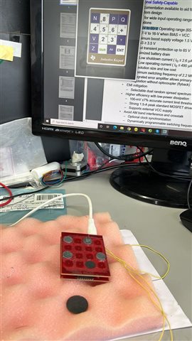
I tried simple POC on the LDC1314-EVK as below but the facing issue of false detection even object is not there on the coil and it is corrected after 15-20 seconds or more time.

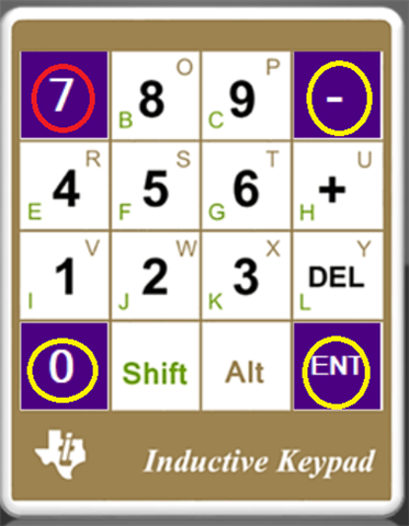
  • Removed the keypad sticker and exposed the coils.
  • Place the thin round metal objects on the coils.
  • As you can see in the attached image, I have placed 5 objects but it is detecting 6 objects.
  • After 15-20 seconds it shows the correct objects.

My question is - Can I use LDC1314 or any LDC series for object detection for my application? I just want to know which chess box has chess pieces is there?

Thanks,

Hitesh

  • Hey Hitesh,

    Thanks for considering to use Texas Instruments.  If I Interpret you picture correctly, Q is the undesired spot that indicates a metal object when a coin is not present.  It is possible that your yellow wires pass too closely to the board especially near that coil and are causing a false reading.  I would try to keep those wires as far from the coil board as possible. 

    I think so long as you properly layout the board, you should be able to use the LDC1314 in this application.

  • Hi Patrick,

    Yes, Q and Z both are the undesired spot. The yellow wire is not causing any issues, if we remove it still the same observation.

    What I observe - is that the undesired spot gets clear after 15-20 sec so, so I believe; when we do row and col scanning it detects the change in coil inductance but when it comes to the 2nd or 3rd scanning iteration it is stable and clear. What is your thought on this?

    If this is the case, how can I solve in my case because in a Chess game, someone can move chess pieces within a 2-3 sec as well?

    Thanks,

    Hitesh

  • Hitesh,

    Patrick is out today.
    Can I propose and experiment with your chess board?

    Remove all but one of the pieces.
    Move the piece to each of the four positions around a common point.
    Do you see false detections for the common point as you move the piece?
    If you do, then the nearby piece is causing the unoccupied/common point to behave as though there is a piece on it.
    You may need to experiment with the device settings or perhaps a different size piece.

    Also, do the sensors at each of the board positions use the same sensor frequency?
    If they do, then they may be coupling to one another, and that may be why you are seeing the undesired spot take so long to clear: the senssors are coupling to each other and a piece is interacting with more than one sensors.

    Regards,
    John

  • Hi John,

    Thanks for your reply in the absence of Patrick.

    Moving a single piece to every four corners is detecting correctly since it is just one piece. When I have multiple pieces, at that it starts detecting wrong.

    In the following image, I have put only a 3-piece in the corner (yellow circle) but I also detect at the red circle which is undesired.

    I am using the Inductive keypad EVK only and the metal piece over is the same to coil size so not overlapping with nearby coil.

    Also, do the sensors at each of the board positions use the same sensor frequency?

    I am putting the same 0.2mm thick SS piece at all the 3 corners. If metal object is same does it means the same sensor frequency?

    Thanks,

    Hitesh

  • Hello Hitesh,

    There will be some variation in the sensor frequency due to pcb manufacturing of the individual coils, tolerance of the capacitor, and tolerance of the different metal pieces.  However, I think you that frequency shift should be rather negligible.  I am starting to think this might be a timing misalignment issue between sampling and sensor selection.  The design documentation states continuous conversion is done with the internal oscillator of the LDC1314 and it looks like synchronization is assumed by checking the INTB pin after waiting 70us after the device was awakened from sleep mode.  It could be that there is a flaw in the code, that causes a subtle deviation from what is outlined in the state diagram (figure 11) of the TI design document.  Or there could be some noise triggering different mux channels to be selected than what are intended.   It might be worthwhile looking at the FSUSB74 SELx pins to see if there is an irregular pattern.  Does false detection happen to any of the squares not at the corners?

  • Hi Patrick,

    Yes, false detection happens at another place as well when more than 4-5 pieces are on the coil matrix. And false detection happens only in row or column where the metal piece is on the coil.

    I will check FSUB74 SELx pins and share the oscilloscope results.

    So, the question again - Is this technology can be used for my application where I need to sense an 8x8 matrix within 1 to 2 seconds and check objects on the coil or not?

    Thanks,

    Hitesh

  • Hello Hitesh,

    This particular EVM was designed to be  a keypad, which typically is intended to only have a single button pressed at time.  Consequently, I do not think the designer tested rigorously enough to discover the issue you are encountering now.  I suspect this issue stems from the microcontroller software.  After we see your oscilloscope results, I think can narrow down whether there is a rogue glitch with the muxes.

    As for the LDC1314 device, I think it is capable of doing what you want so long as the system is properly designed.

  • Hi Patrick,

    Is it possible to have the LDC1314 keypad source code so we can modify the scanning time and threshold to validate it further?

    Thanks,

    Hitesh

  • Hey Hitesh,

    When you installed the GUI it should actually have saved the source code on your computer.  I think you should be able to find in a path similar to this:

    C:\Program Files (x86)\Texas Instruments\TIDA-00509 Inductive Keypad-1.0\EVM Firmware