This thread has been locked.

If you have a related question, please click the "Ask a related question" button in the top right corner. The newly created question will be automatically linked to this question.

HDC2010: Applying offset error correction mentioned in HDC3 Silicon users guide

Part Number: HDC2010
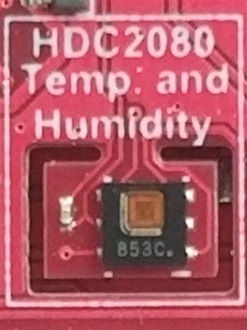
Other Parts Discussed in Thread: HDC2021, HDC2080, HDC2022, MSP-EXP430F5529LP, ENERGIA, BP-BASSENSORSMKII, TMP117

Hi,

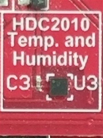
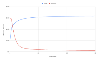
I have been maintaining an IOT environmental sensor which features the HDC2010 sensor. We have been observing a positive humidity offset in these devices - the how and why of the offset is well documented in other forum posts. In-field calibration is not an option, and their environment cannot be well controlled. I am considering migrating to the HDC30xx series for future designs, but we already have thousands of pieces of hardware already manufactured.

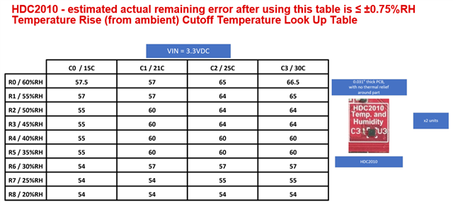
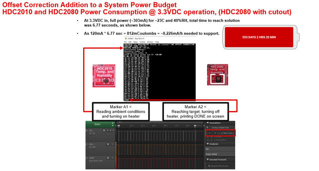
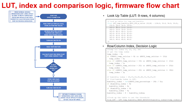
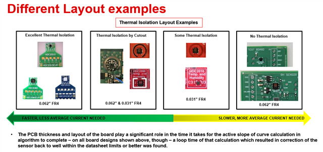
My question was whether the "Offset error correction" procedure shown in the HDC3 Silicon users guide could be applied to the HDC2010? The HDC2010 also has a heater - so I don't see why the same theory could not be applied.

If so, would there be any differences in the procedure, and how would I acquire the correct lookup table? Are TI able to provide one, or provide the methodology for generating one?

Any comment would be appreciated.

Cheers,

Tim Lamborn.

  • Tim - 

    Thanks for the post - that is correct. The same algorithm works with HDC2010, HDC2080, HDC2021 and HDC2022.

    Specifically for the HDC2010, for this layout example on 0.62" board, with no cutout, i was able to capture this LUT : 

    Energia file - runs on MSP-EXP430F5529LP and uses BP-BASSENSORSMKII BoosterPack - you can use the LP and your own hardware. 

    TMP117 is commented out, so if you ever get that BoosterPack, you can use the TMP117 from this code as well. 

    HDC2_RH_OFFSET_CORRECTION_BASS_MKII_0x40_01_27_2022.ino

    Using that, I was able to capture and then calculate the power budget as well

  • Thanks for the reply Josh.

    I have been testing this the past few days, and am having some trouble reaching the required temperatures.

    Just to confirm my understanding of the algorithm in plan english, with example values in brackets.

    1. Read ambient values: [ ambient_temp = 25c, ambient_hum = 55% ]
    2. Lookup required temperature rise: [ rise_temp = 64c ]
    3. Run heater until temperature exceeds ambient_temp + rise_temp: [ final_temp = 89c ]
    4. The offset is the final humidity, which will be zero for an ideal device: [ final_hum = 0% ]

    In most cases the required final temperature will be around 90 degrees. I can barely get my HDC2010 to reach 70 degrees after 2 minutes of heating.

    I am running the HDC2010 at 3V3. Our thermal isolation is poor - so this may be part of the problem. I also tested this on a Mikro Click DK https://www.mikroe.com/temp-hum-3-click, and couldn't get above 65c. This board may have no thermal isolation, but its relatively small, and I connected it via wire wrap - so I would have expected an alright thermal performance.


    I suppose my questions are:

    • Is my understanding that we need to reach ~90 deg c correct?
    • Can you think of any reason besides thermal layout that we would be limited to 70 deg?
    • Can you recommend any next steps?

    Cheers,

    Tim Lamborn.

  • Tim - 

    Can you share a picture of the HDC part on your PCB?

  • Is there any way I can share these privately with you?

  • Here's an image of the part on the part (U6). The PCB is 1.6mm, 4 layers. Note that on each layer the copper is poured into the keepout, mitigating the cutout somewhat. The rest of the PCB is approximately 10cm sq. I'm happy to share much more detailed information - including images from a thermal camera - if you can provide a private way to share this.
     

  • Tim - 

    Sorry for the delay - so your board looks similar/cross between these two styles. 


    and the LUT I shared with you previously applies basically to both of them  - so you could start there and then go to each temp/%RH setting, run the algorithm and check and adjust as required to match exactly what you produced. 

  • Hi Josh,

    None of my devices - even brand new ones assembled by a CM under recommended conditions - converge to 0% humidity when heated.

    Here is one device after 60 seconds of heating. It converges to a stable temperature with a humidity offset of ~2%. This device is brand new, and I get similar results from the Mikro dev kit - which I expect to have been assembled in a clean environment.

    I could just assume that devices will converge to 2% on this design, and any residual humidity above this is the error - but this assumption concerns me.

  • Tim  - you need to baseline your units first against a reference to see how far they are off. Then to get LUT values, run heater to known error %RH and capture the heat rise value for LUT, per setpoint entry. Then you can average out all the results, per setpoint to get LUT to check and tweak as needed.