This thread has been locked.

If you have a related question, please click the "Ask a related question" button in the top right corner. The newly created question will be automatically linked to this question.

IWRL6432: Modifying antenna geometry support in 5.2 SDK

Part Number: IWRL6432

Hello TI Supporters,

I try to design custom antenna for IWRL6432.
I already check out other engineer's question linked as "IWRL6432: Elevation Estimation and Parameters of Antenna Geometry", "IWRL6432: Parameters of Antenna Geometry".

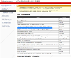
In a release notes of SDK 5.2, there is a new feature "Antenna geometry configuration support Motion and Presence Detection OOB Demo".

However, I am not sure this is the support function associated in the questions linked above.

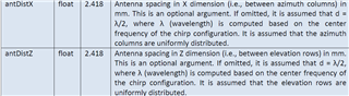
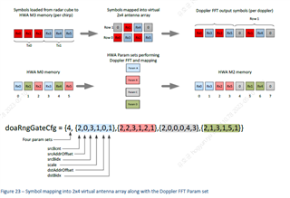
Actually, I need to design new antenna with spacing 0.7 lamda.
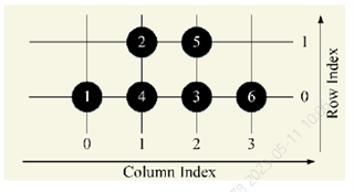
I would like to know how to set the parameters for 2x4 virtual antenna with 0.7 wavelength spacing like EVM as below figure.

Teach me the way to set parameters of custom antenna array by my self.

Regard.

  • Hi,

    The threads which you have linked describe the process to do this with the previous version of the SDK but  with the release of SDK 5.2 and the addition of the antennaGeometryCfg CLI command this has been made much simpler. 

    Please see section 3.2.5 (Antenna Pattern Configuration) of the parameter tuning guide. The guide can be found at <SDK_INSTALL_LOCATION>/docs/MotionPresenceDetectionDemo_TuningGuide.pdf. This section describes how to modify the CLI command for custom antenna layouts. 

    Best Regards,

    Josh

  • Hi Josh,
    Thank you for the answer.

    Q1.
    But, Now I have a trouble already asked not working Visualizer linked as "IWRL6432BOOST: Visualizer of new SDK is not working"
    So, it is not possible to use SDK5.2 right now.

    Do you guess my board works on the visualizer of previous SDK(5.1) with downloading cfg as configured in SDK 5.2?
    I did't try yet, but I am worried about visualizer in SDK 5.1 normally works.
    Because Configuration parameters are quite different from each SDK version.

    Q2.
    According to the document you mentioned, Virtual antenna array seems to be the same distance from each element in column index.
    I thought that it is from the spacing of between TX antennas and among RX antennas.
    Is it possible to have different spacing between TXs and among RXs? (For example TXs have 0.7 lamda and RXs have 0.5 lamda spacing in column way.)

    Q3.
    In the section 3.2.5 Antenna Pattern Configuration, there is a picture of EVM board part.
    It looks different because the crystal oscillator in my EVM is on the other side of the PCB.
    Doesn't it cause that the crystal affects to radiation pattern?

    Appreciate your support.
    Regard.

  • Q4.
    I check the command "antGeometryCfg".
    Parameter "antDistX" & "antDistZ" mean the spacing distance, but there is no vaild range.
    I want to know the range what value can be set.

  • Hello,

    1. I do not believe that you will be able to run the demo with SDK 5.2 configuration on the SDK 5.1 visualizer. As you mentioned, many of the configuration parameters have changed so I would expect several errors. 

    2. I suppose this would depend on the spacing between the elements in the resulting virtual antenna array. From the document you can see that the descriptions for antDistX and antDistZ mention the distance between elements is assumed to be evenly distributed.

    3. The picture of the EVM from that section in the guide is of a Rev. A EVM. The crystal oscillator was moved to the back of the board for Rev. B EVM for this reason. 

    For Q4 I am looking into this and will get back to you with an answer tomorrow. 

    Best Regards,

    Josh

  • Hello,

    Firstly about your answer of Q3, I understand this as that affecting the radiation pattern by the crystal is the reason why you moved crystal to the opposite.
    Is it?


    About the answer of Q2, I thought my question is not clear to understand you.

    Of course, the elements spacing of virtual antenna array is depend on the physical TX and RX antenna geometry.
    I meant it is possible to have different gaps.
    To get it easier, I attached a figure.

    It seems (A) and (B) must be same.
    But, is it possible that all different lamda can be applied for (A), (C), (D)?

    While you have been answering my questions, I can't wait for another SDK covered all issue.

    Hope you reply me and wish SDK be improved soon.

    I will wait for answer of Q4 too.

    Regards.

  • Hello, 

    Please accept my sincere apologies for the delay here. 

    Firstly about your answer of Q3, I understand this as that affecting the radiation pattern by the crystal is the reason why you moved crystal to the opposite.
    Is it?

    Yes, Crystal on the top side was causing high DC/low frequency elevation as it is very close to antenna, Hence moving from top to bottom showed improvement in the DC component. This is explained in the below e2e thread.

    https://e2e.ti.com/support/sensors-group/sensors/f/sensors-forum/1186915/iwrl6432boost-as-for-iwrl6432-evm-rev-a--b-is-there-any-performance-result-to-share-with-us?tisearch=e2e-sitesearch&keymatch=crystal%2520iwrl6432#

    It seems (A) and (B) must be same.
    But, is it possible that all different lamda can be applied for (A), (C), (D)?

    Yes, A and B must be the same. And D must also be the same (A=B=D). C does not need to be the same however. 

    If A,B,D is not the same we will have nonuniform spatial sampling.  Typically we want them to be lambda/2. Where lambda corresponds to Tx frequency in the middle of the ADC acquisition period.

    Parameter "antDistX" & "antDistZ" mean the spacing distance, but there is no vaild range.
    I want to know the range what value can be set.

    There are no specific limits on the values that can be input but please keep in mind the following.

    Below is a figure showing azimuth angle as function of azimuth FFT spectrum index, (blue line), for d=lambda/2. The edges of the FFT correspond to +/- 90 degrees of azimuth angle. If we increase distance, d>lambda/2 we would get red curve, while if we decrease distance, d<lambda/2 we get green curve. For example with “red curve” case, we increase accuracy but the azimuth filed of view is reduced.

    Best Regards,

    Josh