A related question is a question created from another question. When the related question is created, it will be automatically linked to the original question.
If you have a related question, please click the "Ask a related question" button in the top right corner. The newly created question will be automatically linked to this question.
We do not offer a spice model for the DRV5013-q1. What are you hoping to simulate with the device? If you want an idea for what kind of output you will see for some magnet moving around the device, you could try the MAGNETIC-SENSE-ENHANCED-PROXIMITY tool under the software development tab on the product page.
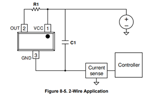
Thank you for your prompt response. We are planning to use it as two-wire application as shown in the datasheet. We need to make it working between 7V to 17V and -40C to 85C for automotive application.
As per my understanding, during OFF state the current will be equal to self consumption. During ON state of the hall sensor, the current will be self consumption and pull low current equal to VCC / (R1 + rDS(on)).
I see current has dependancy on temperature and supply voltage. How we can predict current during ON and OFF state over the oerating temperature and supply voltage?
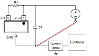
Also, we need to detect, hall output (pin#3) to GND and Supply. How we can detect it? Is current sense will have different value compared to operating condition (ON and OFF state of the Hall sensor)?
Could you recommend interface circuit where we can detect hall output over the operating temperature and input voltage as well as detect short to battery and short to ground?
It is the reason, I was looking for the SPICE model. If you have other tool, that would be great.
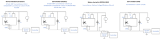
According to figure 6-2 in the datasheet, we would expect the self consumption or Icc to be between 2 and 3 mA for your supply range and the allowable temperature range. If you set R1 to the recommended minimum of 500Ω, the absolute max expected current you might expect through the closed Drain source is 17V/500Ω=34mA (neglected Rdson since the minimum is not specified in the datasheet). If you were to short OUT to VCC, the magnetic field was greater than BOP, and your supply had negligible internal resistance, we might expect the sensed current to be 7V/50Ω = 140mA or greater. Therefore, I think you should be able to detect short to battery. Similarly if battery is shorted to DRV5013 device ground, I think you should sense a very large current. If output is shorted to ground, then it would be difficult to discern electrically. But it could be revealed through swapping magnet polarties and consistently seeing greater than 3mA at your current sensor during the manufacturing process.
Thank you for your reply. I didn't get how you come up with 50Ohm resistor and 140mA current. It would be great if you explain bit more.
I agree with the calculation of current, for 7V supply and 500Ohm pull up,
Imin = 7/500 = 14mA, and I max = 17/500 = 34mA
Therefore, current sense will detect 2 to 3mA during off state (as specified in datasheet) and 16mA to 37mA.
During short to battery, MOSFET might conduct through though internal body diode of the MOSFET, Correct me if I am wrong. I tested one hall sensor similar to DRV5013. What i see is during short to battery is, it is continously drawing approximately same amount of current compared to when Hall sensor is ON.
for the short to GND, I would expect zero current measured in the current sense.