This thread has been locked.

If you have a related question, please click the "Ask a related question" button in the top right corner. The newly created question will be automatically linked to this question.

AWR2944: Flashing Issue

Part Number: AWR2944
Other Parts Discussed in Thread: , UNIFLASH, DP83TC812R-Q1

Hi,

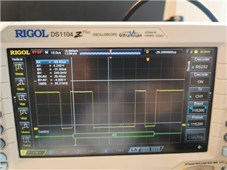
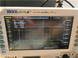
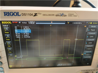
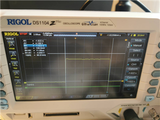
We have designed a custom board based on the AWR2944EVM board. While we can flash the AWR2944EVM ok using the J8 USB port and XDS110 debug probe, we are having issues doing this on the custom board. I was able to flash the XDS110 MCU ok with the latest firmware using the steps listed here - https://software-dl.ti.com/ccs/esd/documents/xdsdebugprobes/emu_xds110.html. However, when I try to flash the AWR2944 chip from command line, using the uart_uniflash.py script provided in the SDK, I get the below:

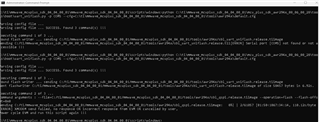
C:\ti\mmwave_mcuplus_sdk_04_04_00_01\mmwave_mcuplus_sdk_04_04_00_01\scripts\windows>python C:\ti\mmwave_mcuplus_sdk_04_04_00_01\mcu_plus_sdk_awr294x_08_06_00_28\tools\boot\uart_uniflash.py -p COM8 --cfg=C:\ti\mmwave_mcuplus_sdk_04_04_00_01\mmwave_mcuplus_sdk_04_04_00_01\tools\awr294x\default.cfg

Parsing config file ...
Parsing config file ... SUCCESS. Found 3 command(s) !!!

Executing command 1 of 3 ...
Found flash writer ... sending C:/ti/mmwave_mcuplus_sdk_04_04_00_01/mmwave_mcuplus_sdk_04_04_00_01/tools/awr294x/sbl_uart_uniflash.release.tiimage
Sending C:/ti/mmwave_mcuplus_sdk_04_04_00_01/mmwave_mcuplus_sdk_04_04_00_01/tools/awr294x/sbl_uart_uniflash.release.tiimage: 0%| | 0/58457 [00:00<?, ?bytes/s]send error: expected NAK, CRC, EOT or CAN; got b'\x07'
send error: expected NAK, CRC, EOT or CAN; got b'\xff'
send error: expected NAK, CRC, EOT or CAN; got b'\x07'
send error: expected NAK, CRC, EOT or CAN; got b'\xff'
send error: expected NAK, CRC, EOT or CAN; got b'\x07'
send error: expected NAK, CRC, EOT or CAN; got b'\xff'
send error: expected NAK, CRC, EOT or CAN; got b'\x07'
send error: expected NAK, CRC, EOT or CAN; got b'\xff'
send error: expected NAK, CRC, EOT or CAN; got b'\x07'
send error: expected NAK, CRC, EOT or CAN; got b'\xff'
send error: expected NAK, CRC, EOT or CAN; got b'\x07'
Sending C:/ti/mmwave_mcuplus_sdk_04_04_00_01/mmwave_mcuplus_sdk_04_04_00_01/tools/awr294x/sbl_uart_uniflash.release.tiimage: 0%| | 2/58457 [00:21<344:09:14, 21.20s/bytes]
[ERROR] XMODEM send failed, no response OR incorrect response from EVM OR cancelled by user,
Power cycle EVM and run this script again !!!

I have tried some of the suggested fixes from other similar threads on the forum (e.g., https://e2e.ti.com/support/sensors-group/sensors/f/sensors-forum/1101390/awr2944evm-soc-initialization-binary-flashing-issue/4081913?tisearch=e2e-sitesearch&keymatch=%22XMODEM%20send%20failed%2C%20no%20response%20OR%20incorrect%20response%20from%20EVM%20OR%20cancelled%20by%20user%22#4081913) without success:

  • Checking if flash device is compatible - we use the GD25B64ESIGR, which is functionally almost identical I think to the GD25B64CWAG listed in this document and used on eval board, https://www.ti.com/lit/an/sprach9d/sprach9d.pdf?ts=1685036305246&ref_url=https%253A%252F%252Fe2e.ti.com%252F.
  • Tried using Uniflash to flash instead of command line (same result as above).
  • Checked device version and looks to be similar to that used on AWR2944EVM board (AWR2944EVM board device markings = XA2944 / BG / 15ZCSS9 / 987, custom board device markings = XA2944 / BG / 1AZCRV9 / 987).
  • No point trying to flash from different computer as I can flash AWR2944EVM board successfully from this computer.
  • Tried using different versions of the mmWave SDK, e.g., mmwave_mcuplus_sdk_04_02_00_02, mmwave_mcuplus_sdk_04_04_00_01.
  • Tried using flashing files attached in above forum thread (sbl_qspi.release.tiimagesbl_uart_uniflash.release.tiimageawr2944_ccsdebug.appimage).

Note that we didn't make any changes to the scripts before flashing. Also, I tried on a 2nd custom board that we had fabricated/assembled and got an identical result to the above there.

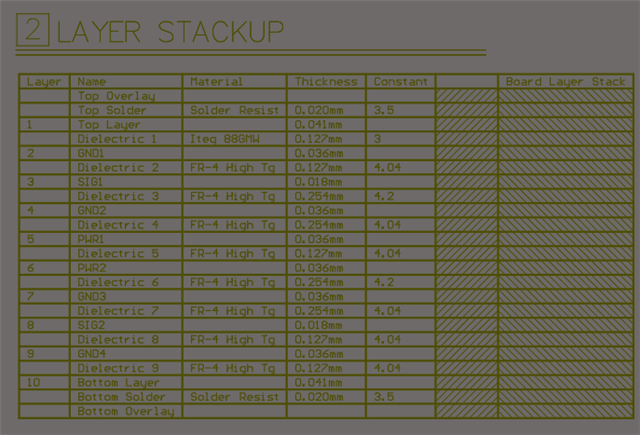
I also rechecked the schematic/layout and I don't see any differences in this section of the board from the AWR2944EVM board. Do you have any ideas on what the issue may be? 

Kind regards,

Peter.

  • Hi Peter,

    An expert will reach out to you for support on this within 24 working hours. Your patience is greatly appreciated. If possible, please feel free to provide any more info that could help us understand the issue better i.e differences between the EVM and your custom board.

    Regards,

    Kaushik

  • Hi Kaushik,

    In terms of differences between the EVM and custom boards, we had to change some of the components in the digital interface / power supply sections due to supply chain constraints as many of the TI ICs used here were not available for > 1 year. Key component changes are:

    • U1 (QSPI Flash) - GigaDevice GD25B64CWAG replaced with GigaDevice GD25B64ESIGR
    • U2 (switching regulator) - TI LM63635DQDRRRQ1replaced with Maxim MAX20006AFOD/VY+
    • U3/U5 (CAN transceivers) - TI TCAN1043ADYYRQ1 replaced with NXP TJR1442ATK/0Z
    • U4 (automotive Ethernet PHY) - TI DP83TC812R-Q1 replaced with NXP TJA1102SHN/0Z
    • U15 (Ethernet PHY) - TI DP83867ERGZR replaced with Microchip VSC8501XML-03
    • U20 (LDO regulator) - TI TPS79601DRBR replaced with TI TPS76733QPWPRQ1
    • U23/U26 (Quad SPDT Analog Switch) - TI TS3A5018RSVR replaced with TI TS3A5018DGVR
    • U33 (LDO regulator) - TI TPS7B8133QDRVRQ1 replaced with TI TPS7A6033QKTTRQ1

    Of these, the only one I can see affecting the flashing of the radar chip is the U1 (QSPI flash) change - the replacement device looks almost identical to me though. 

    The XDS110 interface is identical on the custom board (same TI TM4C1294NCPDTT3MCU used here) and the routing between QSPI flash and AWR2944 almost identical to the eval board.

    I checked voltage rails and they look fine:

    • 1V0 = TP17 = 1.002V
    • 1V2 = TP18 = 1.202 V
    • 1V8 = TP16 = 1.800 V
    • 3V3 = TP15 = 3.328 V
    • 3VIO = 3.327 V
    • 5 V = 4.978 V

    The board stackup is very similar (top image below is custom board, bottom image below is eval board) - main changes here were to add another laminate to give an extra routing layer and to swap out between L1-L2 the Rogers RO3003 (which fabricators find hard to work with) for Iteq 88GMW (which we have used successfully on many boards before).

  • Is there any guidance you could give me on what the problem might be here? Thanks

  • I tried there to update the XD110 to the latest firmware (3.0.0.25) and also set the serial number to be the same as the AWR2944EVM, in case this was causing a problem - now see the below when I enter 'xdsdfu -e' on command prompt:

    <<<< Device 0 >>>>

    VID: 0x0451    PID: 0xbef3

    Device Name:   XDS110 Embed with CMSIS-DAP

    Version:       3.0.0.25

    Manufacturer:  Texas Instruments

    Serial Num:    RA290032

    Mode:          Runtime

    Configuration: Standard

    I'm still seeing above issue however, i.e., I cannot flash firmware onto the AWR2944 successfully. When I just open a serial connection to J8 / Application/User UART COM port I get the below coming through, i.e., same alternating 0x07 / 0xFF that happens when I try to flash firmware.

    With the AWR2944EVM I get the below, i.e., ASCII 'C' character coming through once a second:


    I reviewed the schematic again for the custom board vs AWR2944EVM and there are no changes in the XDS110 section so I'm puzzled as to what is going on here. When might I expect a reply? As it is now a week since my original post and I'm a bit lost as to what the problem may be.

  • Hello,

    I am looking into your issue and will also involve someone from the software team. Please allow me a couple days to get back to you.

    Thanks,

    -Shareef

  • Hi Shareef,

    I have got a bit further with debugging of this problem - I tried probing the MSS_UARTA_TX line from the AWR2944 (accessible at R128 0-ohm resistor) on the AWR2944EVM board and the custom board.

    I can see on the AWR2944EVM board that we get 0x43 ('C' character in ASCII) being sent every 3 seconds at expected baud rate of 115,200.

    On the custom board it looks from the below that a 0x43 is being sent but that the baud rate is closer to 90,910:


    When I use this baud rate both the oscilloscope decodes it correctly:

    Hterm output is now as below – it seems to generally be 0x43 and then gets a burst of 0x30 transmissions, as can be seen in oscilloscope screengrabs.

    I then modified the uart_uniflash.py script to use 90,910 baud rate, rather than defined 115,200 baud rate. This allowed the flash writer to be correctly flashed, however it seems to hang on the 2nd flashing step (bootloader).

    When I look at the MSS_UARTA_TX line from the AWR2944 towards the end of the 1st flashing step I get the below, whereby 0x06 bytes (presumably acknowledgements from the AWR2944, I can see same being sent on AWR2944EVM during flashing step) are sent every 115 mS or so at 90.91 KHz. At the end of the flashing step the line voltage drops to around 1.92 V and stays there.

    This all seems very strange to me - why is the AWR2944 operating at a non-standard baud rate of around 90,910, rather than 115,200? Do you think there is a problem with the AWR2944 devices we have assembled onto the boards? In which case we could try replacing them with a more recent version of the chip? Ours are XA2944BGALT pre-production parts that were ordered in approximately December 2021 directly from the TI website. I can see that there is 476 of the AWR2944ABGALTRQ1 chip in stock on 

  • Have figured it out now - the problem was that on SOP3 and SOP4 (which indicate to the AWR2944 what external crystal reference frequency is used) both the pullup and pulldown resistors were fitted. When I removed the pullup resistors R301 and R309 I was then able to flash the custom board ok. The confusion came from the AWR2944EVM Altium files having both marked on the schematic as 10 Kohm so I had fitted both (although I see now that the exported BOM for the AWR2944EVM is correct in having both R301 and R309 not fitted).