This thread has been locked.

If you have a related question, please click the "Ask a related question" button in the top right corner. The newly created question will be automatically linked to this question.

TMCS1108-Q1: Output Voltage Mismatch on Datasheet

Part Number: TMCS1108-Q1

Hello E2E Experts,

Good day.

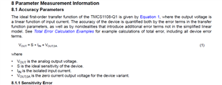
I am using TMCS1108-Q1 current sensor IC. According to the datasheet the Vout equation I can't get proper output voltage at the Vout pin.

In this condition when my led strip, which I have connected to p1 and P2, the Vout=0.28v, and in the off condition I get 0.333V.

Please give me a one-solved example of how to calculate the Vout from the given equation.

Regards,

CSC

  • CSC,

    The equation you screenshotted is the equation for output voltage of the device. Vout,0A is based on the fed supply voltage to the device (pin 8), and in the given diagram you are feeding 3.3V, so this should be 1.65V for the 0A mark (A2B is showing in the schematic). If you are seeing 0.33V, then you are actually using the unidirectional variant of the part (AxU). Then, the current passed through the lead frame of the device will be amplified by the sensitivity and added to the 0.33V. Note that current that flows from the IN- pins to the IN+ pin will be seen by the device as a negative current and will be subtracted from the 0.33V. 

    The way the diagram is configured above, the device is set up to measure any current that flows through either TR1, or through the C1/R5 filter in parallel, and out to LOAD_O/P. This is the only current the device will measure as this is configured. Was this what was intended?

  • Thank you for your response. 

    My actual question is if I want measure current through this given equation and also through software using this equation how to i find it?

    if possible give one solved example use of Equation which is given in screen shot.

    Also i attached my 2nd schematic i have to also find current and voltage using this equation. 

  • Also want to mention i use unidirectional Ic TMCS1108-Q1u

  • Damini,

    To determine the current in SW, you would simply need to unpack it in the reverse order. So, for a given measurement,

    - subtract the known reference voltage (VOUT - 0.33V). This will give you the current magnitude only (with a negative value representing current flow in the opposite direction)

    - Divide the resultant above by the sensitivity of the device to determine the current at the input. 

    I am actually supporting this second schematic on a separate thread here

  • Thank you for your response.

    I want to ask you that what is the minimum limit of  Ac current measure by this TMCS1108-Q1? 

    Can I measure current up to 200maA or below it? 

  • Damini, 

    This is going to be dependent on the frequency of the AC signal, and the bandwidth of the device. Check out the specs of the noise floor from the datasheet:

    To determine the peak to peak noise of the device, you would need to multiply the above number for the appropriate device by the square root of the desired bandwidth, and then multiply that result by 6 (for a 3 sigma two tailed approximation of 99%). This will give you your peak to peak noise referred to the output, and you can divide that by the sensitivity to refer to the input. To reduce the noise level, you can filter the output which will help you achieve better resolution on the AC signal, but this will be at the expense of bandwidth. 

  • Hello,

    Thank you for the response but i think this is not my answer .

    I am asking about current measurement.
    What is the minimum amount i am measuring AC current ?
    Also want to know can i measure below or up to 200micro ampere current with this IC? 

  • Damini,

    The above is the correct answer here. If you are looking to measure an AC signal, the AC signal strength must be greater than the magnitude of the noise floor to be detectable (this is called signal to noise ratio). 

    From the datasheet snippet I posted above, you can calculate for the A2 variant from my instructions above that the RMS noise is (330uA/sqrt(Hz))*(sqrt(80kHz) = 93.3mArms, peak to peak noise is (2.95mVrms)*6 = 560mApp, referred to the input. What this means is that at full bandwidth, a signal with an amplitude of less than 560mA will at worst be undetectable, and at best, highly distorted due to the noise. If you filter the output and reduce the BW as a result, this will also lower the noise floor of the device, and therefore your SNR will improve, but you also will lost the ability to detect higher frequencies. Based on my results, I would say that the textbook answer to your question "What is the minimum amount i am measuring AC current," for full bandwidth, would be 560mApp, but higher SNR results in less distortion. 

    With the understanding you are looking for 200uA resolution, not 200mA, I do not think this is going to be achievable with any Hall effect sensor, let alone the TMCS110x family. They are simply too noisy to achieve this level of resolution.

    Please check out this TI Precision labs video for more instruction on this topic. 

  • Thank you for your response .

    Actually I want to measure up to or below 200mA AC current in to AC load. 

  • Damini,

    200mA may be achieveable, but you will need to reduce the bandwidth considerably to ensure the noise floor is low enough to detect this magnitude of change. Based on that bandwidth reduction, it may disqualify the device due to the frequency falling outside the bandwidth. Are you looking to measure a sinusoidal signal, or something more complex (triangle wave, sawtooth, square, etc.)?