This thread has been locked.

If you have a related question, please click the "Ask a related question" button in the top right corner. The newly created question will be automatically linked to this question.

AFE3010-EVM: working on DC Supply

Part Number: AFE3010-EVM
Other Parts Discussed in Thread: AFE3010

Hi,

I am working on AFE3010EVM to generate Ground fault Current interrupt and its working fine. But my point is without Connecting  AC Line to PH pin of AFE3010 is it possible to Achieve Same Results.

Because When I remove JP9 Jumper, SCR is not generating Pulse During Fault Condition.

  • Hello valued engineer,

    I am looking this over and will respond shortly.

    Sincerely,

    Peter

  • Hello,

    So the AFE3010 uses the PH pin to detect and create a clock that is based off the zero-crossings of the oscillating line voltage it is pulled up to. 

    The device uses this “clock” or line zero crossings to determine how many cycles it has measured a fault and how long to fire SCR. 

    Thus, I don’t think it is possible to run the device without a clock (without pulling the PH and SCRTST pin up to an oscillating voltage between 45 Hz and 70Hz.

    Sincerely,

    Peter

  • Thank you Peter for your Support

  • Hi Peter,

    When I Powered on AFE3010 SCR immediately Fires One Pulse even if I am not Performing Self test (SEL = Open), Is it Possible to Disable this Activity.

    Because I am Unable to Identify Ground Fault through Software when System Contains Leakage Current DURING Power on AFE3010.

    Regards,

    Manohar S

  • Hey Manohar,

    Are you supplying a clock to PH (jumping JP9) and SCRTST pins? Can I get information on how your jumpers are configured and how your line and VDD/DC Supply cables are to through EVM?

  • The device is probably failing one of its continuous self-test which are watch-dog timers at PH and SCRTST pin that are constantly looking for line zero crossings. If no zero crossings are detected for ~100ms, the AFE3010 will fire SCR.

  • Hi peter,

    I am Using Opto-isolator Between PH Pin and AC Supply by this I am Able to make AFE3010 Work on DC Supply. As you said if Clock is not generated SCR Will not Fire, but as per Above Changes whenever I am leaking Current as per thresh hold  set by FB Resistor SCR is triggering from this I can conclude Clock is generating.

    My only Concern is there any possibility to Disable All kind of Self tests.

  • When SEL pin is in Open condition Self test should not Perform but still During Initial Power up time immediately SCR Generating Pulse. I want to know why this pulse is generating.

  • 1.This is how I am Sourcing DC Voltage to the PH Pin

    2. I removed JP8 Jumper and Feeding +20VDC at R10 Resistor.

    3. JP2 and JP9 Jumpers are removed.

    4. JP5 Jumper is removed to disable the Self test

  • Hello Manohar,

    Floating the SEL pin only disables the SCR self test.

    Given that you still have JP6 connected (SCRTST connected to SCR anode) and you have floated the SCR anode ( opened JP2). You are floating SCRTST pin which will yield a failure with the continuous self test at SCRTST pin. Which will cause device to fire SCR pin right at power up..

    To fix this you need to short the SCRTST and PH pins together so they are seeing the line zero crossings.

    Sincerely,

    Peter

  • Hi peter,

    Now I am Operating AFE3010 on AC Power Supply  During Self test (SEL=GND) SCR Fire Continuously, Can you Please suggest what is the reason for this.

    Note: Circuit Configuration as per SBFS042 Evaluation Guide

    Regards,

    Manohar S

  • Hello Manohar,

    What happened in your previous configuration when/if you connected SCRTST and PH pins together?

    With your new configuration (powering AFE3010 from AC Power Supply) are you using the AFE3010EVM?

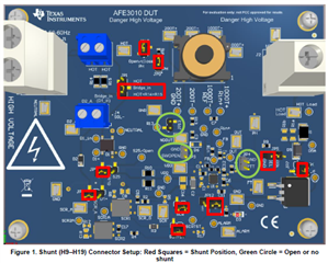
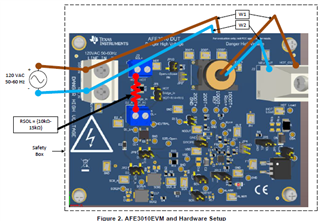
    If so have you setup you circuit as shown in Figure 1 and Figure 2 of the AFE3010EVM User's Guide?

    I do have one note about your previous configuration (power AFE3010 with DC supply). You sent a simulation schematic saying this is how you were driving the PH pin with voltage (VoutDC) being half wave rectified, but it really should not be. The PH pin was designed to be pulled up to a fully oscillating, large voltage line signal. Theoretically the PIN voltage is clamped to 20V and 0V, but this is a square wave, not a half-rectified sinusoid. Thus, this could have been the error here.

    Sincerely,

    Peter

  • Hi peter,

    Ans1: After Connecting PH and SCRTST Pin Together Still Self Test is Failing (During Power on SCR Fires and Alarm Continuously Blinking).

    I connected AFE3010EVM As per User Guide and Measure SCRTST Pin It Requires Around 50VDC. 

    From this I came to Conclusion that For PH and SCRTST what I am Sourcing is not Enough to Detect Zero Crossing and Phase of the Signal.

    If I Use DC Source to Drive AFE3010, in Present Design I can't Source that much Voltage to PH and SCRTST pins. so that I am Using AC Power Supply only.

    Ans2: Now I am Operating AFE3010EVM in AC Power Source (Connected As per Images mention Above by Peter) and I make SEL = Open and Performing Self test Manual By Using PTT Pin and its Working. 

    I am Using SW_Open pin to Reset AFE3010 After Fires SCR During Fault Condition.

    Q1: I want final One Clarification on Self test:

    If I connect SEL = Ground it will conduct Self test and Fires SCR  for every 180 Cycles When Self test get Pass. is this Statement is Correct.

    Regards,

    Manohar S

  • Hello Manohar,

    You can operate the AFE3010 when supplying the device with a 20V DC source. The only stipulation is that the PH and SCRTST need oscillating signals and there are 2 ways to do this: use large pull-up resistors to the high-voltage line signal or drive them directly with 0V to 20V square wave that has the same frequency and phase as the line voltage source you are measuring leakage on.

    Note the above situations only work when SEL is floating because I assume you are not needing the SCR self test and thus you are not connecting SCRTST to SCR anode. If you do want the SCR self test, then you must connect SCRTST to SCR anode with a ~50kOhm to 68 kOhm resistor and the SCR must be tied to line via the diode and solenoid as shown in the typical application schematic.


    Q1: Your statement is partially correct. When SEL = GND, the AFE3010 will perform the SCR self-test. When SEL=float, AFE3010 will NOT perform the SCR self test, but will still perform all other continuous and periodic self tests.

    There are two periodic self-tests that both occur every 180 cycles: fault test (FT) and SCR self-test. The periodic SCR self-test happens right after the FT self-test. During the SCR self test, the SCRTST pin bias the SCR anode and looks for a normally operating SCR. If the SCR is not working/damaged, SCRTST pin will detect this during the SCR self-test and repeat again once every 60 cycles, for a total of 5 times. Upon the 5th failure, device will determine the SCR is not working, fire SCR pin, and blink ALARM.

    If the periodic self test passes, then SCRTST pin goes back to high-impedance and device remains in a ready mode.

    The only time AFE3010 fires SCR upon a passing a self test, is when the AFE3010 passes the initial self-test activated due to pressing the PTT/SWOPEN pin. This is shown in Figure 11, 13, and 14 of the datasheet. Every other instance where device passes self-test, nothing happens.


    Sincerely,

    Peter

  • Hi peter,

    1. actually when I Make SEL=Open (Alarm Blink ones and off) SCR is not Firing because FT and SCR self-test are Passing and SCR is only Fire when I making PTT pin Low. From This I conclude that AFE3010 Self test is passing.

    2. when I Connect SEL=GND SCR Fires Continuously I am Not understanding why this Happening can you please clarify on this it will help me to Close this Thread

  • Hello Manohar,

    This means that the SCR self test is causing the failure. Remember, there is no SCR self test when SEL=float. However, there will always be the FT self test.

    Can you please clarify your statement: “SCR Fires Continuously”? Is the SCR being activated repeatedly or is it just the ALARM that is continuously blinking, once per second? Usually if SCR is firing repeatedly you can hear the solenoid buzzing, but if you’re using a resistor to emulate solenoid you need to probe SCR pin or current across solenoid resistor to verify that SCR is actually turning on and off continuously.

    Whenever SCR is repeatedly firing, this is due to a supply voltage dropping to low value (<10V) and causing a device reset. Once device resets it resets fault counters and fires SCR again which pulls down VDD again, thus this is a loop.

    I recommend probing the SCR and VDD pins and monitor right at and after power up with SEL=GND. If VDD is collapsing, then you need to increase capacitance at VDD pins.

    If SCR is not firing continuously and it only fires once, then device is failing SCR self test. Try reducing the “solenoid” resistance to something <10k. 

    The best way for me to help is to probe pin voltages (OUT, SCR, VDD, Line) at power up with a duration of 200ms using an oscilloscope. Also a picture of your EVM configuration and complete schematic for any component changes made.

    Getting this system to work can be difficult because any little change or missing just one connection can cause failures. 

    Sincerely,

    Peter