This thread has been locked.

If you have a related question, please click the "Ask a related question" button in the top right corner. The newly created question will be automatically linked to this question.

BOOSTXL-PGA460: High resolution echo waveform with multiple devices

Part Number: BOOSTXL-PGA460
Other Parts Discussed in Thread: PGA460, ENERGIA

Hi there,

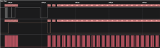
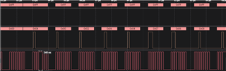
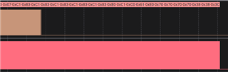
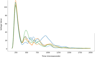
We are investigating ultrasound attenuation through various devices. We've found that due to the short distance over which we are transferring the pulses, there is some capacitance between the transmission and receive lines in bi-static mode, and we are therefore seeing a spike in signal at the very start of the waveform that is obscuring the signal. From our understanding, this shouldn't be there, and when looking at an oscilloscope attached to a transducer, we don't see the spike. See the below figure for an example of this spike:

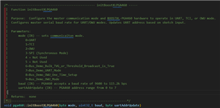
To overcome this, we have purchased another PGA460 board to separate the transmission of the ultrasound pulse from the receiving so that we eradicate the capacitance issue. However, we also require the high resolution data that is available from selecting DSP - LP Filter on Graph Mode on the data monitor page.

This doesn't seem easily available when using UART and working from the BusDemo Energia sketches. I've seen some mention of using SPI to get the digitised ADC signal and then doing our own DSP, but I'm not particularly electronically savvy and was just wondering if we could get some guidance on how to get high-resolution ADC waveforms using one PGA460 board to transmit the signal and one PGA460 board to receive the signal.

Thank you for any help you can provide Slight smile

Jack

  • Hello Jack, 

    Thanks for posting to the sensors forum!

    That is correct in order to get rid of the spike you are seeing at the start of the signal you would need the additional PGA460. The issue here is not really a capacitive issue as noted, rather its internal noise coupling from the drive circuit during a pulse command into return circuitry, so its not inherent to the design of the board but just internal to the part itself. The spikes are reduced compared to what you would see in a monostatic system but not equivalent to what you would see in an ideal bi-static system.

    The higher resolution data that you are referring to above is called Direct Data Burst, this is raw digital data that can be extracted from the device at various points of the digital signal path controlled using the DP_MUX register, see image below:

    You can still command the device to perform a measurement using a standard UART command, but note that the UMR command 5 is not valid in this mode. Collecting burst data is only works through USART so using UART to collect this data is not possible. Reason being is that this mode requires a clock on the clock pin, to get the data during direct data burst, all the data will be output on the TXD pin. Keep in mind that the CLK pin to provide clock pulses until all the data has been transmitted and all the data will be passed, there is not start or stop in the USART frames, they are all essentially data frames until you receive the checksum at the end. The packets are transmitted form LSB to MSB in 8 bit segments. One thing to note is that USART is not enabled or disable 

    Getting two EVMs to should not be too difficult since you can use the same communication lines for each board UART is addressable so you can just change the address on each of the devices. You can set one device to burst and the other one to listen, you will need to do this through energia since the GUI does not support this. We were working on trying to get this implemented onto the GUI so you may see some options for this but it was never completed so the settings will crash the GUI.

    I hope this helps!

    Best,

    Isaac

  • Hi Isaac,

    Thank you so much for your speedy reply. I think I understand what you are saying about how to get the Direct Burst Data, but I'm still not super clear on how to implement it in code.

    Is there any chance you could provide me with a little bit of code extract on how to receive the full data burst? Slight smile

    Jack

  • Hey Jack,

    I wasn't able to locate the code we have for this function on the GUI, but I can at least provide scope captures of what is happening in the data lines.

    White waveform is RXD, brown is TXD, and the red is the CLK. So here we send a burst and listen command to start the measurement and we start running the clock in 8 bit chunks:


    During this entire time the clock will need to run and the data is collected from the TXD pin so at first you should see a lot of zeroes but eventually you will start to receive data as shown below:

    The length of time you collect data for is dependent on the record length you have configured on the sensor. Once the data is complete you will see the TXD pin pull low to zero and remain there. In our code the clock runs a little longer than the configured record window just to ensure that every bit of data is collected. Here is another capture.

    Best,

    Isaac

  • Hi Isaac,

    Thank you for your response. However, I'm still very unsure as to how I would translate this into code I can run on Energia in order to get out the full waveform. As mentioned, I'm really not electrically literate, so the scope captures have confused me even more!

    I can see in the PGA460_USSC.cpp file found in the Energia library that there is communication over SPI - is this what you mean when you are talking about USART?

    Do you have any idea how would poll the TXD pin from this code?

    Really appreciate your help - this area is not my forte!

    Jack

  • Hello Jack,

    Correct the Energia library already has a configurations to support the USART,which is labeled as SPI communication on this library. You just have to initialize the device in the correct mode. For example in the GetDistance example, you will see this function called: initPGA460(); but it does not have any arguments in the function.

    If you go to the PGA460_USSC.cpp file you can see exactly what this function is doing, see screenshot below but it takes one argument for communication mode and one for UART address update. This means you need to send a 3 for the SPI or USART communication mode and a zero if you wish to keep the UART address the same.

    I think a similar comparison of how to sample large amounts of data can be seen in the function pullEchoDataDump(byte element). This outputs 128 bytes of data from the echo data dump that are sampled by the MCU. In the direct data burst option you would have to collect a larger amount of data compared to a single read. The amount of data mainly depends on the length of your record window but you might be able to model the collection after this pullEchoDataDump example. Look at the SPI where comm == 3.

    I hope this helps!

    Best,

    Isaac

  • Hi Isaac,

    Thank you for that - I will give it a go today. I had been poking around this code myself, but I was under the impression that the pullEchoDataDump function was only able to sample the 128 bytes of data from the internal memory on the PGA460 board, and that this could be done at any point in time after an ultrasound command was sent.

    For the direct data burst, should I try and pull data in a similar way? - I see the SPI comm mode uses the function spiMosiIdle to do this. Again here I believed it was extracting data from internal memory, not reading directly from the TXD line as you have recommended previously. 

    I want to say again how much I appreciate your help on this - already been very useful!

    Jack

  • Hello Jack,

    Slight correction I meant pullEchoDataDumpBulk. And slightly correct, the pullEchoDataDumpBulk function samples the 128 bytes of data stored in internal PGA460 memory but it is all passed to the MCU via the TXD pin just like the direct data mode is. The main differences between the two as you mentioned is that the echo data dump is requested after a measurement command is completed but the direct data is collected as soon as you send a burst and listen command so you have to collect it right away. 

    So your function will not look the same as the pullEchoDataDumpBulk formula, because you wont have to request the data you essentially have do away without that part of the function and essentially start collecting as soon as the burst is requested.

    else if (comm == 3) // SPI
    	{
    		// run read bulk transducer echo data dump command on first iteration
    		byte buf7[3] = {syncByte, TEDD, calcChecksum(TEDD)};
    		spiTransfer(buf7, sizeof(buf7));
    		// MOSI transmit 0xFF to pull MISO return data
    		spiMosiIdle(129);
    		for(int n=0; n<128; n++)
    		{			
    		   bulkString = bulkString + "," + misoBuf[n];		   
    		}
    		return bulkString;

    Some tips for writing your function:

    The function you create could be setup to return an error if your PGA460 is not configured in SPI mode, since the SPI will only work for direct data mode. This is not necessary but might be nice to have.

    The byte buf7[3] and spiTransfer(), lines would not be needed because these send the command to the device to pass the bulk data do the MCU.

    As you mentioned above the spiMosiIdle function will just forces the MCU communication line high to allow data to stream from the PGA460 to the MCU and collect that data. The value 129 is the number of expected bytes, so this number will need to be larger to accommodate for all the data.

    The for loop value for n < 128 indicates how many packages are going to be read. This will need to be changed depending on your record length so this value goes hand and hand with the value you entered in spiMosiIdle. Keep in mind to make this value larger than it needs to be as it can always be fine tuned to be smaller. This will create a string with the values separated by a comma stored in bulkString, but the function can be reworked to save your data in another way if thats better for you. This might be an easy way to go to a CSV format though.

    You can use the ultrasonicCmd function to send the measurement command at the beginning of your function of course.

    Always glad to help out let me know if you have any other questions!

    Best,

    Isaac

  • Hi Isaac,

    Okay some progress - I am communicating via the SPI protocol - but I am only getting 0s (or technically nothing as the code below doesn't print if it is just a 0) off of the line after triggering the P1 Burst and Listen command!

    Here is the code I have created to both trigger a burst and record the Direct Data Burst:

    /*------------------------------------------------- runEchoDirectDataBurst -----
     |  Function runEchoDirectDataBurst
     |
     |  Purpose:  Runs a preset 1 or 2 burst and or listen command to capture the full direct data burst.
     |
     |  Parameters:
     |		preset (IN) -- determines which preset command is run:
     |			• 0 = Preset 1 Burst + Listen command
     |			• 1 = Preset 2 Burst + Listen command
     |			• 2 = Preset 1 Listen Only command
     |			• 3 = Preset 2 Listen Only command
     |			• 17 = Preset 1 Burst + Listen broadcast command
     |			• 18 = Preset 2 Burst + Listen broadcast command
     |			• 19 = Preset 1 Listen Only broadcast command
     |			• 20 = Preset 2 Listen Only broadcast command
     |
     |  Returns:  comma delimited string of all direct data burst values
     *-------------------------------------------------------------------*/
    void pga460::runEchoDirectDataBurst(byte preset)
    {
    	if (comm == 3) // SPI
    	{
    		// enable Echo Data Dump bit
    		regAddr = 0x40;
    		regData = 0x80;
    		byte writeType = SRW; // default to single address register write (cmd10)
    		if (preset > 16)	  // update to broadcast register write if broadcast TOF preset command given
    		{
    			writeType = BC_RW; // cmd22
    		}
    
    		byte buf10[5] = {syncByte, writeType, regAddr, regData, calcChecksum(writeType)};
    		spiTransfer(buf10, sizeof(buf10));
    		// delay(10);
    
    		// run preset 1 or 2 burst and or listen command
    		pga460::ultrasonicCmd(preset, 1);
    
    		// disbale Echo Data Dump bit
    		regData = 0x00;
    		buf10[3] = regData;
    		buf10[4] = calcChecksum(writeType);
    		spiTransfer(buf10, sizeof(buf10));
    
    		// Read out full amount of data
    		readFullDirectDataBurst();
    	}
    	else
    	{
    		// do nothing
    	}
    	return;
    }
    
    /*------------------------------------------------- readFullDirectDataBurst -----
     |  Function readFullDirectDataBurst
     |
     |  Purpose:  Bulk read out all bytes of the direct data burst from the latest burst and/or listen command.
     |		This is only valid for SPI mode, and must be performed directly after a burst and/or listen command,
     |		as there is no storing of the signal on the PGA460 board.
     |
     |  Parameters:
     |		none
     |
     |  Returns:  comma delimited string of all direct data burst values
     *-------------------------------------------------------------------*/
    void pga460::readFullDirectDataBurst()
    {
    	if (comm == 3) // SPI
    	{
    		// run read bulk transducer echo data dump command on first iteration
    		// byte buf7[3] = {syncByte, TEDD, calcChecksum(TEDD)};
    		// spiTransfer(buf7, sizeof(buf7));
    		// MOSI transmit 0xFF to pull MISO return data
    		spiMosiIdleFullData(16000);
    	}
    	else
    	{
    		// do nothing
    	}
    	return;
    }
    
    /*------------------------------------------------- spiMosiIdleFullData-----
     |  Function spiMosiIdleFullData
     |
     |  Purpose:  Forces MOSI of 0xFF to idle high master output, while
     |			MISO pin returns all direct data burst values
     |
     |  Parameters:
     |		size (IN) -- number of MISO data bytes expected from slave
     |
     |  Returns: none
     *-------------------------------------------------------------------*/
    void pga460::spiMosiIdleFullData(byte size)
    {
    #ifdef EnSPI
    	// memset(misoBuf, 0x00, sizeof(misoBuf)); // idle-low receive buffer data
    	digitalWrite(SPI_CS, LOW);
    	while (true)
    	{
    		digitalWrite(SPI_CS, LOW);
    		// misoBuf[i] = usscSPI.transfer(0xFE);
    		misoValue = int(usscSPI.transfer(0xFE));
    		if (misoValue != 0)
    		{
    			Serial.println(misoValue);
    		}
    		digitalWrite(SPI_CS, HIGH);
    	}
    	digitalWrite(SPI_CS, HIGH);
    	return;
    #endif
    }

    I am triggering this from the Energia sketch like this after the standard initBoostXLPGA460() and defaultPGA460():

    void loop() {
      Serial.println("Getting data:");
      Serial.println(ussc.runEchoDirectDataBurst(edd-1));
      delay(5000);
    }

    Without much luck!

    The SPI line only produces 0s. My current suspicion is that I need to send a command to the PGA460 in order to trigger it to send the correct data down the SPI line, but I don't know how to do this. I also thought that it could be worth setting the TEST_MUX register to 0x01 (the value for digital LP Filter to be sent), which I have tried to do in defaulPGA460() like the below, but also with no luck:

    	if ((comm == 0 || comm == 2 || comm == 3) && (comm != 6)) // USART or OWU mode and not busDemo6
    	{
    		byte buf12[59] = {syncByte, EEBW, USER_DATA1, USER_DATA2, USER_DATA3, USER_DATA4, USER_DATA5, USER_DATA6,
    						  USER_DATA7, USER_DATA8, USER_DATA9, USER_DATA10, USER_DATA11, USER_DATA12, USER_DATA13, USER_DATA14,
    						  USER_DATA15, USER_DATA16, USER_DATA17, USER_DATA18, USER_DATA19, USER_DATA20,
    						  TVGAIN0, TVGAIN1, TVGAIN2, TVGAIN3, TVGAIN4, TVGAIN5, TVGAIN6, INIT_GAIN, FREQUENCY, DEADTIME,
    						  PULSE_P1, PULSE_P2, CURR_LIM_P1, CURR_LIM_P2, REC_LENGTH, FREQ_DIAG, SAT_FDIAG_TH, FVOLT_DEC, DECPL_TEMP,
    						  DSP_SCALE, TEMP_TRIM, P1_GAIN_CTRL, P2_GAIN_CTRL, EE_CRC, EE_CNTRL, BPF_A2_MSB, BPF_A2_LSB, BPF_A3_MSB,
    						  BPF_A3_LSB, BPF_B1_MSB, BPF_B1_LSB, LPF_A2_MSB, LPF_A2_LSB, LPF_B1_MSB, LPF_B1_LSB, TEST_MUX, calcChecksum(EEBW)};
    
    		if (comm == 0 || comm == 2) // UART or OWU mode
    		{
    			Serial1.write(buf12, sizeof(buf12)); // serial transmit master data for bulk EEPROM
    		}
    		if (comm == 3) // SPI mode
    		{
    			spiTransfer(buf12, sizeof(buf12));
    		}
    		delay(50);

    Weirdly, I do get some values coming down the line when I connect the board to the GUI, flash it, get it to do an LP Filter mode echo waveform, and then upload the Energia sketch. Very peculiar...

    Any ideas? It would be amazing to get the code extract they use in the GUI to do this, although I believe you said you couldn't find this. Hopefully, mine and your hard work will benefit someone else in the future who also wants to do something similar!

    Jack

  • Hey Jack,

    I wasn't able to review your response today, but let me see if I can find the code for the PGA460 EVM to see if I can provide that to you. I will get back to you on Monday.

    Best,

    Isaac

  • Hi Isaac,

    Thank you - I appreciate it Blush

    Jack

  • Hello Jack,

    I was able to find the source code for the GUI firmware, but the code was not written an a very readable manner so its difficult to figure out what is really going on in the code. I believe it would be better to work through the Energia sketch that you have started.

    I noticed some issues when reviewing your first chunk of code up above:

    1. I see that you enabled the data dump on the EE_CNTRL register. We are not using this mode so the lines of code that set the values and write this to the device are not required. Data dump will  not provide data until you perform a command 7 instruction but this will only provide the 128 bytes.

    2. I didn't see any DP_MUX configuration to select data multiplexer output. This is register 0x4B the first three bits. If this is not configured the device will not enter direct data burst mode. This would explain why there were only zeroes being picked up via the SPI lines. Enter this configuration before sending the pga460::ultrasonicCmd(preset, 1);

    3. Remove direct data burst disable code since this should never have been enabled.

    Setting the TEST_MUX to 0x01 outputs the AFE output directly to the TEST pin, so this is not the operational mode that you are looking for in your system, so make sure this is configured back to zero. Hopefully this should yield better results than before.

    Best,

    Isaac

  • Hi Isaac,

    Unfortunately, still have no luck.

    1. I've disabled the Data Dump Bit at the EE_CNTRL address.

    2. I believe the TEST_MUX and DP_MUX info is stored at the same address at 0x4B. I've tried only setting the DP_MUX to 0x01 through to 0x04, as well as a variety of other combinations. See below photo:

    3. I'm unsure which bit of the code you mentioned here.

    I've managed to understand the code much better and can now write and read from registers reliably; however, I'm still not getting out the data I want. I have removed any delay from the pga460::ultrasonicCmd(preset, 0) function, and I now get something down the SPI line: 64, 0, 0, 191, 0, 0, 0,...,  but after the 191 it is 0s indefinitely. I am thinking that this might just be the response to the ultrasonicCmd function.

    Here is my updated code. Note that I am cycling through multiple values to set the DP_MUX/TEST_MUX register to get it working, but nothing has succeeded:

    void pga460::runEchoDirectDataBurst(byte preset)
    {
    	if (comm == 3) // SPI
    	{
    
    		// Set DATA_MUX register to allow for Direct Data Burst:
    		// 0x01, 0x02, 0x03, 0x04, 0x09, 0x0A, 0x0B, 0x0C, 0x81, 0x82, 0x83, 0x84, 0xA1, 0xA2, 0xA3, 0xA4
    		byte dataMuxVals[16] = {0x01, 0x02, 0x03, 0x04, 0x09, 0x0A, 0x0B, 0x0C, 0x81, 0x82, 0x83, 0x84, 0xA1, 0xA2, 0xA3, 0xA4};
    		regAddr = 0x4B;
    		// regData = 0x01;
    		for (size_t i = 0; i < 8; i++)
    		{
    			Serial.print("DATA_MUX Value = ");
    			Serial.println(dataMuxVals[i]);
    
    			registerWrite(0x40, 0x00);
    			delay(10);
    			registerWrite(regAddr, dataMuxVals[i]);
    			delay(10);
    
    			Serial.println("Value written.");
    
    			Serial.println("Reading value back.");
    
    			pga460::registerRead(regAddr);
    
    			Serial.println("Sending ultrasound command");
    
    			// run preset 1 or 2 burst and or listen command
    			pga460::ultrasonicCmd(preset, 0);
    
    			// Read out full amount of data
    			readFullDirectDataBurst();
    
    			pga460::registerRead(regAddr);
    
    			Serial.println("Data received, restarting.");
    
    			delay(1000);
    		}
    
    		Serial.println("Done.");
    	}
    	else
    	{
    		// do nothing
    	}
    	return;
    }
    
    
    void pga460::readFullDirectDataBurst()
    {
    	if (comm == 3) // SPI
    	{
    		unsigned long length = 1000000;
    		spiMosiIdleFullData(length);
    	}
    	else
    	{
    		// do nothing
    	}
    	return;
    }
    
    
    void pga460::spiMosiIdleFullData(unsigned long size)
    {
    #ifdef EnSPI
    	// memset(misoBuf, 0x00, sizeof(misoBuf)); // idle-low receive buffer data
    	digitalWrite(SPI_CS, LOW);
    	for (unsigned long i = 0; i < size; i++)
    	{
    		digitalWrite(SPI_CS, LOW);
    		misoValue = int(usscSPI.transfer(0xFF));
    		if (misoValue != 0)
    		{
    			Serial.print(i);
    			Serial.print(", ");
    			Serial.println(misoValue);
    		}
    		digitalWrite(SPI_CS, HIGH);
    	}
    	digitalWrite(SPI_CS, HIGH);
    	return;
    #endif
    }

    If there is some way I could look through the relevant GUI code, I could try and shed some light on what I should be doing. Otherwise, I'm not sure what is going wrong!

    Jack

  • Hello Jack,

    If you could send me a friend request so we can talk over private message.

    Best,

    Isaac