This thread has been locked.

If you have a related question, please click the "Ask a related question" button in the top right corner. The newly created question will be automatically linked to this question.

IWR6843: IWR6843

Part Number: IWR6843
Other Parts Discussed in Thread: , UNIFLASH

Hi,


this thread didn't help me.

Referring to the Data Path User Guide , the non-interleaved complex data or real data in the adcbuf memory of IWR6843 is stored as:

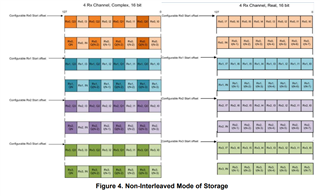
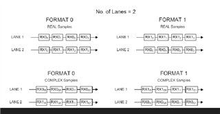
and the output on LVDS in Non-interlaleaved mode for 2 data lanes can be : 

data lane 0  | rx0_sample0_real | rx0_sample0_imag| ... | rx0_sampleN-1_real | rx0_sampleN-1_imag |...| rx1_sample0_real | rx1_sample0_imag| ...               

data lane 1  | rx0_sample1_real | rx0_sample1_imag| ... | rx0_sampleN_real     | rx0_sampleN_imag    |...| rx2_sample0_real | rx2_sample0_imag| ...

                                               or 

data lane 0  | rx0_sample0_real    ... | rx0_sampleN_real  |...........| rx4_sample0_real    |...| rx4_sampleN_real  | ...               

data lane 1  | rx0_sample0_imag | ... | rx0_sampleN_imag |............| rx4_sample0_imag  |...| rx4_sampleN_imag | ...

my Questions are:

Is it possible the configure IWR6843 so that the output of Data on the LVDS lanes are macthing with the second on?

Is yes, how to set it ?

Best Regards,

joseph

  • Hi  Joseph, 

    To get the data in format such that real samples are sent on data lane 0 and complex samples on data lane 1, no configuration is available in the cfg file.

    You will have to make below modifications in the code

    In the file mmwave_sdk_03_06_00_00-LTS\packages\ti\drivers\cbuff\src\cbuff_lvds.c , In line no 300 and 301 need to be modified as below

      case 2:
    {
    /* Two Lanes: */
    if (ptrSession->sessionCfg.dataType == CBUFF_DataType_REAL)
    {
    format0Value = CBUFF_LANES2_REAL_FMT0;
    format1Value = CBUFF_LANES2_REAL_FMT1;
    }
    else
    {
    format0Value = CBUFF_LANES2_REAL_FMT0;
    format1Value = CBUFF_LANES2_REAL_FMT1;

    You need to build drivers libraries after the code is modified.

    Regards,

    Abhishek

  • Hello Abhishek,


    Your answer helped me very well, now I have another challenge. I want to build a BSS bin file (named xwr68xx_radarss.bin in mmWave Studio) and an MSS bin file (named xwr68xx_masterss.bin in mmWave Studio) based on the change I made in cbuff_lvds.c. How do I do this?

    Regards 
    Joseph

  • From BSS and MSS binaries, I want to build a metaimage bin file and pre-flash it for my application to skip the SPI firmare download step of mmWave Studio and enable pass through SPI control of the IWR6843

  • Hi Joseph,

    There is no need to build xwr68xx_radarss.bin as the changes that you are doing are not related to that binary. With the modified binary you will not be able to use mmWave Studio as the changes in firmware are not expected in mmWave studio environment.

    You need to build the mmwave_sdk_03_06_00_00-LTS\packages\ti\demo\xwr68xx project in SDK which will generate xwr68xx_mmw_demo_dss.xe674 and xwr68xx_mmw_demo_mss.xer4f files based on the changes to the source code that you have done and the makefile will generatea single flashable binary  xwr68xx_mmw_demo.bin which will combine xwr68xx_radarss.bin, xwr68xx_mmw_demo_dss.xe674, xwr68xx_mmw_demo_mss.xer4f

    Regards,

    Abhishek

  • Hi Abhishek, 

    i don't know how to build the ....\xwr68xx project in SDK  and i don't also know how to combine xwr68xx_radarss.bin, xwr68xx_mmw_demo_dss.xe674, xwr68xx_mmw_demo_mss.xer4f.

    Which tools i need for both Tasks? 

    kann you explain please or can you recommand me a tutorial, that i can follow to achieve both tasks?

    Regards,

    Joseph

  • Hi Joseph,

    Please refer to the SDK user guide for build instructions. You can find the user guide at

    mmwave_sdk_03_06_00_00-LTS\docs\mmwave_sdk_user_guide.pdf

    Refer to the section "Developing using SDK" in the user guide. It has build setup instructions and procedure to build the demo

    Regards,

    Abhishek

  • Hi Abhishek, 

    I followed all the build instructions but after flashing the iwr6843 part with the generated metaimage bin file.

    I was not able to issue mmWave link commands via SPI as I did previously with the metaimage bin file I generated from BSS and MSS found here

     ". ..\Nmmwave_studio_02_01_00_00\rf_eval_firmware\radarss\xwr68xx_radarss.bin" and here

    "...\Nmmwave_studio_02_01_00_00\rf_eval_firmware\masterss\xwr68xx_masterss.bin"

    I don't know if I need to take into account another parameter to generate a .bin metaimage file that will allow me to set up the iwr6843 via SPI as is done with mmWave Studio using the iwr6843ISK evaluation board.

    Regards, 

    Joseph

  • Hi Joseph,

    In the SDK environment, you will not be able to send APIs over SPI. You will have to use the cfg file with the CLI commands. These commands are sent over UART. Please check if you area able to operate with the cfg file without any modification i.e. with pre built binaries and then check with the modification

    You can find the cfg files in the folder mmwave_sdk_03_06_00_00-LTS\packages\ti\demo\xwr68xx\mmw\profiles

    Regards,

    Abhishek

  • Hi Abhishek,

    Currently, my aim is to refrain from transmitting API's over SPI using the SDK environment. Instead, i intend to utilize the SDK environment to construct the "firmware_metaimage.bin" based on the modifications made to the source code. Once this firmware_metaimage.bin is generated, my plan is to load it using UniFlash.

    Upon successful loading of the firmware_metaimage.bin, the IWR6843 device will be able to establish communication with an external host processor through SPI. Consequently, the device can be configured and controlled by the external host processor through the exchange of specific commands over the SPI interface.

    During testing, i have observed that the IWR6843 device can be effectively configured and controlled from external host processor over SPI when i load the "metaimage" built from the BSS and MSS firmware located at "C:\ti\mmwave_studio_02_01_00_00\rf_eval_firmware\radarss\xwr68xx_radarss.bin" and "C:\ti\mmwave_studio_02_01_00_00\rf_eval_firmware\masterss\xwr68xx_masterss.bin," respectively. this BSS/MSS firmware are provided after downloading mmWave Studio.

    However, i encountered an issue whereby the IWR6843 device loses its configurability and controllability through the external host processor over SPI when i load the "metaimage.bin" derived from building the mmwave_sdk_03_06_00_00-LTS\packages\ti\demo\xwr68xx project. This issue persists even when i work with either the default source code or my specific modifications.

    Thus, my primary concern is to address this problem effectively. I seek guidance on the necessary modifications to the SDK source code that will allow us to build the "firmware_metaimage.bin," thereby enabling seamless configuration and control of the IWR6843 device through the external host processor via SPI.

    Regards,

    Joseph

  • Hi Joseph,

    You cannot achieve the same functionality of xwr68xx_masterss.bin using the SDK framework. SDK framework is designed for building the OOB or other demos. Moreover, it is not possible to modify xwr68xx_masterss.bin. Builds done using SDK framework will NOT accept SPI APIs

    If you intend to use the mmwavestudio framework, then try using the below configuration in the studio for changing the LVDS format in DataConfig Tab

    Regards,

    Abhishek

  • Hi Abhishek,

    i understand your point now concerning SDK. 

    When Lane Format = Format 1 is selected, the even complex samples will be directed to Lane 1, while the odd complex samples will be directed to Lane 0, as illustrated in the picture below. No other changes will be made.

    Hence, my consideration was that the required adjustment should be made within the drivers' source code. Subsequently, upon implementing this change, a new MSS firmware can be built to accommodate the modifications accordingly.

    does that mean it's impossible for me to reach my goal? since I can't get the same functionality from xwr68xx_masterss.bin using the SDK environment.

    Could there be another approach to generating MSS firmware that offers the same flexibility as mmWave Studio's MSS firmware ?

    Regards

    Joseph 

  • Hi Joseph,

    As you cannot modify xwr68xx_masterss.bin, only way that you can have desired configuration for LVDS is using the SDK environment.

    In the SDK environment, you need to create an application which will have the LVDS configuration that you desire and at the same time support SPI based APIs.

    The reason I asked you to take a look at the mmwave studio configuration of LVDS is that you could use the same xwr68xx_masterss.bin but send only the LVDS configuration as a modified SPI API. You can try it out in mmwave studio whether the configuration that you select in mmwavestudio result in the format you want and if so, send the same API through SPI from the external host

    Regards,

    Abhishek

  • Hi Abhishek,

    Regrettably, the Lane format format 0 and format 1 provided by mmWave Studio do not align with my objectives.

    Regards 

    Joseph

  • Hi Joseph,

    I would recommend modifying the SDK demo to support the LVDS format you desire and support the SPI APIs

    You will have to remove the data processing part of the code in the demo and retain only the SPI API part. 

    Regards,

    Abhishek 

  • Hi Abhishek,

    i don't know how to do it, can you recommand some tutorial, or documents about how to do it.

    Regards 

    Joseph

  • Hi Joseph,

    You can refer to the below sections in the SDK user guide located at mmwave_sdk_03_06_00_00-LTS\docs

    Developing Using SDK

    MMWAVE SDK Deep Dive

    Regards,

    Abhishek