This thread has been locked.

If you have a related question, please click the "Ask a related question" button in the top right corner. The newly created question will be automatically linked to this question.

TMP411: Wrong readout of the external temperature sensor

Part Number: TMP411

Hey,

We designed a custom variant of a ti dlp reference board (TMP411-Q1) to readout the build-in temp sensor in the DLP.

At the moment we are using the TI light crafter gui to control and read out the sensor values of the ti board and also our board.

We can only readout the internal temperature sensor of the TMP411 correct.

For the external temperature it looks like that there is a offset.

After powerup of the board we get always 0°C back and after some operation time (the dlp warms up, not measured yet but would guess DLP temp is >30°C) the external temperature readout also increase. 

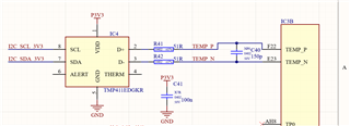
W checked the schematic of our board many time and didn't see any issue there.

We also have the same circuit for a different board where it works quite well.

Have you an idea what can lead to such a behavior?

 Many thanks

Best Christoph

  • Hi Christoph,

    What is the state of the OPEN bit in the Status Register?

    My initial thought is that you have an open solder joint. The reported temperature may increase with leakage currents at higher temperatures. The OPEN bit would indicate that the device sees a fault, and the remote temperature isn't real.

    Your design may also have excessive parasitic capacitance relative to the reference design. The remote sensor cannot handle a lot of capacitance; please see Figure 6 in the datasheet.

    Remote junctions are sensitive to EMI, but they tend to report a positive temperature error in the presence of EMI.

    ren

  • Hey,

    The status register is 0x88 (Open bit = 0; Rlow=1) until the external temperature is >0°C then it is 0x80 (Open bit =0; Rlow=0; Rhigh=0).

    So it looks like that there are excessive parasitic capacitance on this diff. lanes.

    As we need a new revision of this board for other reasons, we will also improve there the layout.

    Many thanks

    Best Christoph

  • If you can take the time to capture the measurement activity on the D+ pin with an oscilloscope, I could confirm whether excessive capacitance is present.

    thanks,

    ren

  • Yes sure, will measure the D+ pin, after I'm back from vacation.

    Thanks