

Part Number: TMP61
Is there a fit replacement for the discontinued KTY81 or KTY82 PTCs?

This thread has been locked.
If you have a related question, please click the "Ask a related question" button in the top right corner. The newly created question will be automatically linked to this question.
Part Number: TMP61
Is there a fit replacement for the discontinued KTY81 or KTY82 PTCs?
Effective March 30, 2023, the KTY81 and KTY82 series of silicon PTC temperature sensors has reached its end-of-life (EOL), as documented in Notice 202301036DN.
In this post, I will introduce the TI TMP61 silicon PTC temperature sensor as a potential replacement for KTY81/KTY82. I will also highlight the functional differences between the sensors, point out the considerations you might need to take for your application (both hardware and software), how your system may be benefited from this change, and the orderable part numbers of the suggested replacements.
In the table seen below, you will find how the KTY81/82 compare to the TMP6X family of devices. These parameters are all considered as they will determine what the best TI replacement option for your system is.
|
Parameter |
KTY8x |
TMP6x Benefits & Implementation Notes |
|||
|
R25°C Options |
10k |
100k |
47k |
1k, 2k |
· More resistance options with less power consumption · Implement software changes to account for effective resistance |
|
Recommended Operating Conditions |
Vsns: 0 to 5.5 V Isns: 0 µA to 400 µA (-40 °C to 150 °C) Automotive: 50 µA to 250 µA (150 °C to 170 °C) |
Vsns: 0 to 5.5 V
Isns: 0 µA to 40 µA |
Vsns: 0 to 5.5 V
Isns: 0 µA to 100 µA |
Isns: 0 µA to 10 mA (25 °C) 0 µA to 2 mA (150 °C) |
· Less power consumption due to lower current drain. · Should consider the voltage supply value when thinking of a replacement |
|
Temp Range |
TMP6131DYAR: TMP6131DYARQ1: TMP6131ELPGM: TMP6131ELPGMQ1: |
TMP6331DYAR: TMP6331DYARQ1: |
TMP6431DYAR: TMP6431DYARQ1: |
-55 °C to 150 °C |
Comparable temp range |
|
Automotive Grade? |
Yes |
Yes |
Yes |
No |
AECQ100 Grade 1 & 0 options |
|
Surface-mount Orderable |
0603 Footprint 10k Ω: TMP6131DYAR |
0603 Footprint 100k Ω: TMP6331DYAR
|
0603 Footprint 47k Ω: TMP6431DYAR |
SOT-23 1k Ω: KTY82/1xx
2k Ω: KTY82/2xx |
85% volume reduction 80% area reduction
Footprint compatible* |
|
Through-hole Orderable |
TO-92S 10k Ω: TMP6131LPGM Automotive: TMP6131ELPGMQ1 |
N/A |
N/A |
SOD70 1k Ω: KTY81/1xx 2k Ω: KTY81/2xx |
48% volume reduction 60% area reduction
Footprint compatible |
*Footprint compatibility explained below
First, let us consider the difference in effective resistance at 25 °C. The lowest resistance of TI’s family of PTCs is the TMP6131 at 10k ohms. This is also the closest to the 1k and 2k effective resistance in your current application. The benefits of this difference are described below. However, this change means that the software processing of the temperature readings should be adjusted to account for the new conversion values. TI recommends the use of the Vbias – Rbias setup as well as a 4th order polynomial method to make temperature conversions faster and more efficiently. For more information on how to create a 4th order polynomial to convert voltage/resistance to temperature using TI’s TMP6Xs, please refer to the following app note. Other common methods are also available for conversion of your data such as a lookup table and Steinhart-Hart model equation. The thermistor design tool allows you to use any of these methods specific to your setup—whether it is current bias or voltage divider bias. For more information about the design tool, refer to the following link.
The next thing to consider is the footprint compatibility. For the surface mount PTC, TI offers a DYA package which may be mounted on the SOT-23 footprint if a quick replacement is needed. As shown below, the DYA can be soldered across pins 1 and 2 of the SOT-23 using the proper solder fillets. Also, since the SOT-23 pads are wider, avoid using excess solder paste to limit the device from rotating during solder reflow.
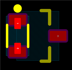
TMP6X DYA sitting on a SOT-23 foot print
On the through-hole footprint, TI’s LPG package is compatible for a pin to pin replacement.
Important Note: because of the internal ESD circuitry of the TMP6x family, these silicon PTCs have a polarity. When assembling this device on an application board: Pin 2 should be on the VHIGH pad, and Pin 1 on the VLOW pad for proper functionality.
Once these changes are taken into consideration, we can talk about the multiple benefits that the TMP6Xs could bring to your current application. With a higher TCR and effective resistance, the TMP6Xs consume less power and have a wider range of sensitivity. Lower power consumption also leads to lower error from self-heating and with a smaller footprint, you could also save space on your board design as seen in the graph below. Please refer to the following preloaded Design Tool for a full functional comparison of the TMP6X vs. KTY82: Thermistor Design Tool - Voltage Bias - TMP6X vs KTY82.zip
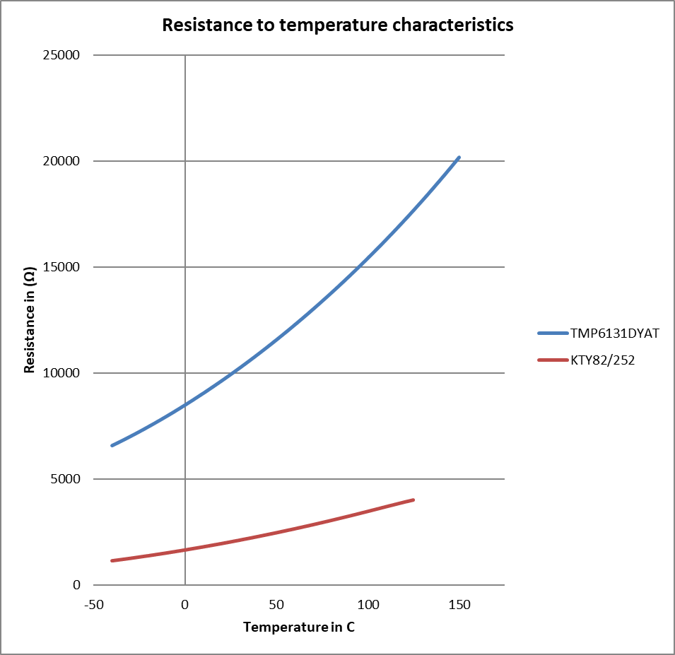 Effective resistance over temperature plot
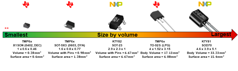
Footprint size comparison
Other benefits include ESD protection due to the internal ESD diode as well as EMI immunity which is attributed to the internal architecture of TI’s TMP6Xs. Our devices also allow for multiple software methods for improving accuracy. These include a 1-point offset calibration, oversampling, and noise filtering techniques—all of which are described in full detail in the following app note.
- Achieve ±1°C Accuracy or Better Across Temp. W/Low-Cost TMP6x Linear Thermistors
