This thread has been locked.

If you have a related question, please click the "Ask a related question" button in the top right corner. The newly created question will be automatically linked to this question.

PGA970: Filtering the LVDT inputs

Part Number: PGA970

Hello;

I am looking into the data sheet and the EVM concerning the input filter from the LVDT to the amplifier inputs

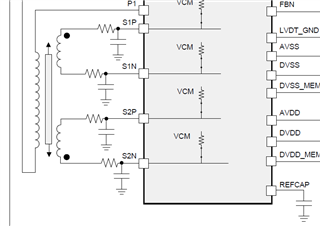
There is a difference between them: At the data sheet there is a RC filter, series resistor and capacitor to GND

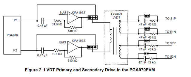
At the EVM the resistor is in series with the capacitor and I can't see how it filters the input.

Since my design is for a noisy environment, can you please advise:

1. Which connection should be applied?

2. What are the components value? Best if you advise value and how to calculate it

3. Can you please advise also concerning the PI to PE filter (at the EVM it is not operative) 

4. Have you more to advise concerning operation in noisy environment?

The left draw is from the data sheet and the right one is from the EVM

Thank you very much

  • Hi Ran Litver,

    1. Which connection should be applied?

    That is difficult to say.  The datasheet is showing a low-pass filter on the secondary side and the EVM has a non-populated filter as well (see schematic).  In addition the EVM includes a  jumper option for a gain stage on the primary side and jumper option for an attenuator on the secondary side.  This is discussed in section 3.1 of the user's guide.  Using the gain method should help overcome some of the noise that could be introduced in the pathway.  You would need to tune the filter(s) based on noise you are attempting to filter relative to the primary AC signal.

    2. What are the components value? Best if you advise value and how to calculate it

    This should be done based on filtering requirements.  You base the filter components on how you want the filter to work.

    3. Can you please advise also concerning the PI to PE filter (at the EVM it is not operative) 

    On the EVM the connection is using a simple loop connection.  A capacitor (C18) could be added and the 0 Ohm resistor (R23) could be replaced with a higher value resistor if filtering is required at this point

    4. Have you more to advise concerning operation in noisy environment?

    Filtering noise can be tricky.  Reducing the noise pickup in the first place is best as opposed to just trying to filter at the ADC input.  Shielded cables is one method.

    Best regards,

    Bob B