This thread has been locked.

If you have a related question, please click the "Ask a related question" button in the top right corner. The newly created question will be automatically linked to this question.

TMAG5110-Q1: Back Biased Gear Tooth detection for Encoder use case

Part Number: TMAG5110-Q1
Other Parts Discussed in Thread: TMAG5110, TMAG5328,

Hello Community,

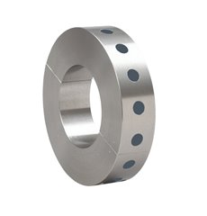
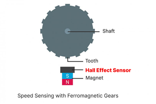
For shaft speed sensing, we want to avoid the installation of magnets/magnetic rings on the rotating shaft & want to leverage a disk with ferrous interrupters such that the following configuration is achieved.

We are looking for a Hall Effect switch for shaft speed sensing with the following requirements:

Method: Utilizing a disk with ferrous interrupters, not direct magnet attachment.
Air Gap: At least 6mm between the sensor and the gear teeth.
Teeth Count: Up to 12 gear teeth on the disk.
Speed: Maximum shaft speed is 6000 RPM.
Distance to MCU: The sensor will be 4m away from the MCU, in an industrial environment.
Output: Compatible with Quadrature Encoder Interface (QEI) on MCU.

Kindly suggest to us:

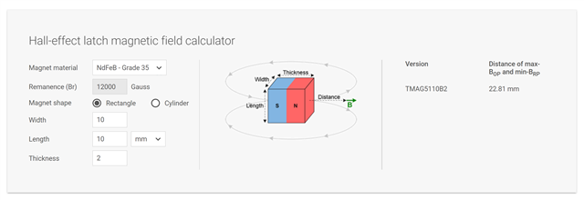
  1. Design resources, application notes or steps for selecting appropriate magent for back-biasing the hall effect sensor.
  2. A suitable switch from TI Portfolio for this application

Looking forward to your guidance & your expert suggestions for our use case.

Regards.

  • Shreeneet,

    Thank you for reaching out on E2E.  The gear tooth sensing application requires very careful alignment of the magnet and sensor such that the sensor is able to cross both operating and release thresholds as each tooth and gap passes.  Since this function works by applying a back bias, the B-field vector should always exhibit the same sign.  The field direction would always be either positive or negative.  As a result using a Latch device for this, such as TMAG5110 cannot work since it would require alternating magnetic field polarity. 

    The target operating point for your switch may vary depending on the size and shape of the magnet, the air gaps between the magnet, sensor, and rotating gear.  It is important to have the switch able to operate at high enough frequency to catch all 24 state changes per revolution.  Based on the tooth count you have indicated and maximum rotation speed (6000 RPM = 100 rev/sec), the output needs to refresh at 2400 Hz.  

    While we do not have any published materials on this particular application, I think it might be easiest to tune your solution using a device such as TMAG5328 (Sample freq = 20 kHz).  This device has a  resistor programmable threshold (2-15 mT) with 1 mT of Hysteresis between Bop and Brp.  In a hypothetical case, you could setup the sensor and magnet such that you had 13 mT at the center of each gap in the gear, and as long as the field at each tooth was greater than 14 mT, you should be able to create a pulsed output from the switch.  

    To create a quadrature output, it would be necessary to have two sensors, and these should ideally be spaced n+1/2 teeth apart about the gear.

    An advantage to using TMAG5238 is that it could be possible to tune each system using a digital potentiometer.  This would allow you to compensate for mechanical tolerances to achieve more consistent performance.

    Thanks,

    Scott

  • Hello Scott,

    Thank you for your guidance. We now understand the relative complexity in the above approach.

    I would like to seek your guidance on the following case, where we need a highly reliable & accurate magnetic pulse counter that gets switched/latched with every passing of a widely spaced magnet.

    What shall be the impact on switching if instead of a continuous multipole ring magnet, we use a discontinuous (6-8 magnets per disk) in collar configuration as shown in the image below

    1. Which Hall Effect sensor is most suitable for this application with the discontinuous magnetic field (radially/axially)?
    2. Can we use a 2D Hall Effect switch/latch for this use case to generate QEI output?
    3. For transmitting sensor data over 3-5m long cables, are any special precautions needed?

    Looking forward to your guidance.

    Regards.

  • Shreeneet,

    For this configuration you may use a 2D Hall-effect latch.  The chief requirements would be that the magnets alternate polarity as you step around the ring, and that you use a strong enough magnet to produce the necessary operating threshold for the latch in both axes.  Assuming that the ring is non-ferromagnetic, then I believe that this should be feasible.  

    Since the output data is in a digital format with either high or low states, noise should not be much of a problem for you over the long cable.  

    Thanks,

    Scott

  • Hello Scott,

    Thank you for the update. We have accordingly selected TMAG5110-Q1 & when I used the Bop & Brp distance calculator on the product page I got the following values. These are highly value-adding tools for quick evaluation. Amazing work sensor division team!

    I am also trying to use the TIMSS Webench simulator to design our use case where multiple magnets are spaced across a ring. I will reach out to you if I encounter any doubts or issues with the simulation study.

    Regards

  • Shreeneet,

    Thanks for the feedback! We are working to make a more complete environment to simplify your development time with the sensor.  The TIMSS tool supports multi-pole ring magnets, but doesn't allow for several discrete magnets, so there may be some discrepancy from the implementation above.  As we continue to develop the TIMSS tool, we are eager to find out challenges that we can address to make it a more practical resource.

    thanks,

    Scott

  • Hello Scott,

    I'm glad to see your goal of making the sensor portfolio evaluation more user-friendly. & yes, a discrete multi-magnet configuration shall be one of the very useful use cases in the TIMSS tool. Especially with the recent storm of technology convergence in Condition-based Monitoring, equipment-level sensors may be seeing a drastic increase in deployment. And having an easy-to-adopt ecosystem from TI for sensor products definitely will become one of the make/break decisions for product teams.

    Seeking insights from your experience on:

    • Impact of a cost-optimized magnetic ring with widely spaced magnets (6x to 10x gap of magnet width) and a latching Hall Effect sensor.

    • Possibility of errors, abnormalities, or waveform issues in this configuration.

    • Precautions for the gap between consecutive magnetic fields and their impact on the timing and phase shift of the output wave fed to the Quadrature Encoder Interface.

    • For instance, can a 2-magnet setup on one ring reliably measure shaft speed (min 500 to max 6000 RPM) when triggering with the South and then North poles?

    Your expert guidance will be invaluable before we perform lab tests with Hall effect sensors.

    Regards.

  • Shreeneet,

    1. As long as the individual magnets are mounted such that alternating poles will be presented to the latch, it should not be a problem to detect the speed of rotation.  
    2. Since the latch operation is primarily concerned with whether or not the field crosses the operating thresholds, the primary concern is to ensure that the magnetic field is strong enough that mechanical tolerances do not result in a missed event. Excessive run-out may result in changing range between the magnets and sensor during rotation.  
    3. For quadrature encoding, you would get more reliable results if the input field is much larger than the operating threshold.  Given this, it would help to place the sensor close to the rotating magnets.  It is important for the 2D latch case that you consider the strength of the field for both field components.  
    4. A two magnet setup should be able to detect the shaft speed provided that the field is above the operating threshold for the sampling period. If the average magnitude is less than the threshold during the sample time, it will not trigger.  In the case of TMAG5110 the sensing bandwidth is 40 kHz, so for any one individual sample occupies 25 us.  It is generally preferred to have at least two samples per pole, so the field would need to exceed the operating threshold for at least 50 us.

    Thanks,

    Scott