This thread has been locked.

If you have a related question, please click the "Ask a related question" button in the top right corner. The newly created question will be automatically linked to this question.

TMP61-Q1: Amplifier Configuration for TMP61 Thermistor Sensor for Remote Temperature Sensing Application

Part Number: TMP61-Q1
Other Parts Discussed in Thread: TMP61, INA351, TLV9062

Hello TI E2E Community,


I am currently working on a temperature-sensing application using the TMP6131ELPGMQ1 linear thermistor from Texas Instruments. The TMP61 sensors are intended to be placed about 3m away from the STM32G474 microcontroller unit (MCU). The application calls for four temperature sensors, each connected to its own ADC channel on the MCU.

The ADC channels on the MCU can accept an input voltage swing from 0 to 3.3V or alternatively 0 to 2.048V/2.5V/2.9V with a 12-bit ADC resolution. We also have access to stable reference voltages of 2.048V, 2.5V, 2.9V, and 3.3V.

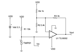
To maximize accuracy and utilize the ADC's dynamic range as effectively as possible, I'm considering using a non-inverting amplifier to increase the output voltage swing from the TMP61 sensor.

My question is: what would be the best approach in terms of designing this non-inverting amplifier? Also, should I use a voltage divider biasing network or an independent constant current source for the TMP61 sensor? Which one would offer greater accuracy?

If there are other ways to improve the signal chain, or if additional information about the system setup or constraints is needed, please let me know.
We are considering using INA351 if that helps or alternatively, a discrete solution with TLV9062 family of OpAmps are available in our inventory.
I appreciate your insights and guidance.

Thank you
  • One option we have been able to optimize based on a manual sweep of varying the Rbias in the voltage divider format is to use a Rbias of 30kOhm at Vbias of 5V.

    TMP61 in a simple voltage divider with Rbias = 30kΩ and Vbias = 5V.

    • At 0°C: R_TMP61_0°C = 8529Ω V_TMP61_0°C = Vbias * (R_TMP61 / (R_TMP61 + Rbias)) = 5V * (8529Ω / (8529Ω + 30000Ω)) = ~0.95V
    • At 170°C: R_TMP61_170°C = 22493Ω V_TMP61_170°C = Vbias * (R_TMP61 / (R_TMP61 + Rbias)) = 5V * (22493Ω / (22493Ω + 30000Ω)) = ~2.5V
    • Vswing = V_TMP61_170°C - V_TMP61_0°C = 2.5V - 0.95V = ~1.55V
    • For ADC 0-2.5V, this covers ~62% of the dynamic range.

    Kindly guide any potential drawback of using a 30kOhm Rbias alongside 10kOhm TMP61 in the voltage divider network in the above configuration, are we missing something obvious here?

  • Hi Neet,

    In this case, no amplifier is needed as you can get an output curve that covers the full dynamic range as you already mentioned.

    At a design level, using an Ibias setup offers more accuracy as you would not be inducing the error of a bias resistor. However, considering that you will have 3 meter long cables/traces, a 1-point calibration is recommended to improve accuracy. This would also account for any bias resistor errors so either setup allows you to get the accuracy that you need. The 1-point calibration and other methods of improving accuracy are described in full detail in the following app note

    Another aspect to consider is that the TMP6X family of thermistors are not resistors and ohms law does not apply when changing the bias resistor. These devices require a bias current--either from a current source or a voltage divider setup. As such, the output curve in an Rbias setup changes depending on the resistor value. If you use a different Rbias than the characterized value (10k ohm), I recommend following the instructions described in this app note to approximate the Voltage/Resistance vs. temperature curve.

    I also recommend looking into the thermistor design tool. This tool describes the different methods to calculate temperature and also shows the output dynamic range with different Ibias (for the current bias setup) and Vbias (for the Rbias setup). Thus, the thermistor tool will help you make design/setup decisions for your application.

    Best regards,

    Simon Rojas

  • Hello ,

    Thank you for your insights. I tried using the thermistor design tool.

    1. We are unable to cover the entire dynamic range as yet the most we have been able to achieve so far with 30kOhm Rbias & 5V input was 1.55V which is ~60% of 0-2.048V ADC Vswing.
    2. Can you help us understand the impact of using a 30kOhm Rbias in voltage divider configuration? I am unable to change the Rbias value in the thermistor design tool, the error prevents us from altering the 10kOhm value.
    3. Can you suggest a low-cost Current source suitable for this use case along with some reference designs that can help us be more confident with the final design for implementing TMP61?

    The ADC channels on the MCU can accept an input voltage swing from 0 to 3.3V or alternatively 0 to 2.048V/2.5V/2.9V with a 12-bit ADC resolution. We also have access to stable reference voltages of 2.048V, 2.5V, 2.9V, and 3.3V.

    Regards

  • Neet,

      The first thing to note is that the TMP6 parts are not resistors. The operate in current mode. The resistance values given are calculated resistances from the voltage feedback of the part. Most of the math for an NTC will not apply here.

    The design tool is a great place to start. to answer your question, if you have a constant current source available go that route. The dynamic range will much greater in constant current mode. The resistor divider circuit automatically divides the voltage in half lowering your dynamic range. The accuracy is still greater than an NTC even with the lower dynamic range. Higher ADC bit resolution will make up for the step size of the ADC and allow you to get the better accuracy. However many customers do not want or can't change the ADC resolution. That's ok we offer two solutions for lower resolutions. One is oversampling and the other is a simple low pass filter that will accomplish the same goal. Both examples are in both of the design tools (Vbias and IBias).

    If you don't have a constant current source available there is a simple low cost solution in the IBias design tool. The preferred solution is to use constant current to get the higher dynamic range, the higher the current the better the TMP6 will be when using the longer wires. The IBias design tool will guide you in setting the highest current and not impede the temperature range. Again its not a resistor so calculating currents are not the same.  

    There is a lot to go through and we can help you get the accuracy that you are looking for. These are great parts but you need to understand how they work in order to get the most from them.

    Also note changing the RBias resistor to a different value than the recommended 10k for the TMP61 will not get the results that you are looking for. Its a current based parts and the only thing that will happen is that the location of the dynamic range will move but not the slope angle. you will not get higher dynamic range. 

    You may want to setup a meeting with the THS guys to get more help. 

  • setup a meeting with the THS guys

    Hello ,

    Thank you for the insights. Can you suggest how do we get in touch with THS Guys? We have a few more queries.

  • Hello  & ,

    We came across a reference circuit design in the SLYY137B - Analog Engineer’s Circuit Amplifiers Temperature Sensing with PTC Circuit on page 306. Following the design steps, we recalculated the values of R4 and R2 to achieve the desired gain and signal level shift. Here are the details of our circuit design:

    Specifications:

    • Temperature Range: 0°C to 170°C
    • ADC Voltage Swing: 0 to 3.3V
    • TMP61: 6400 ppm/°C TCR
    • Supply Voltage: 0 to 3.3V
    • Required Gain: 3V/V
    • R1 = 10 kΩ
    • RPTCMin ≈ 8.4 kΩ
    • RPTCMax ≈ 19.28 kΩ
    • Vtemp Min 0°C: 1.43V
    • Vtemp Max 170°C: 2.27V

    Circuit Design:

    Step 1: Input Voltage Range
    VinMin = (3.3 V * 8.4 kΩ) / (8.4 kΩ + 10 kΩ) ≈ 1.43 V
    VinMax = (3.3 V * 19.28 kΩ) / (19.28 kΩ + 10 kΩ) ≈ 2.27 V

    Step 2: Gain Calculation Gideal = (3.25 V - 0 V) / (2.27 V - 1.43 V) ≈ 3.06 V/V

    Step 3: Parallel Combination of R2 and R4 R2R4ideal = (3 kΩ) / (3.06 - 1) ≈ 1.18 kΩ

    Step 4: Final Resistances Calculation
    R4 = (3 kΩ * 3.3 V) / (2.27 V * 3.06 - 3.25 V) ≈ 1.02 kΩ (Round to 1 kΩ)
    R2 = (1.18 kΩ * 1 kΩ) / (1 kΩ - 1.18 kΩ) ≈ 2.36 kΩ (Round to 2.4 kΩ)

    Summary:

    • R1 = 10 kΩ
    • R2 = 2.4 kΩ
    • R3 = 3 kΩ
    • R4 = 1 kΩ
    • Gain ≈ 3.06 V/V

    We would appreciate your expert suggestions on adding a filter capacitor to minimize noise in the signal. The TMP61 will be connected 2-3m away from this circuit. Additionally, we need guidance on the cutoff frequency design for this case. We have the capability to oversample the signal on the ADC using hardware peripherals on our MCU - STM32G474.

    Looking forward to your valuable insights and feedback.

  • Hello Neet,

    I am the Applications & Marketing Manager for the Temperature & Humidity Sensing (THS) team, our Applications Engineering team is directly involved with supporting queries via this E2E forum, I also noticed you have another question (linked below) in addition to this one, that our team is supporting.

    If you would like, we can arrange meeting with our team. We would collaborate with the local field sales team in your region to make this happen. If this interests you, please let us know. We can reach out to you using the e-mail you registered with on E2E.ti.com, given we get your permission.

  • Hello ,

    Indeed, we would appreciate the support.

    We want to incorporate TMP61-MQ1 sensor into our temperature monitoring use case.

    We have 4 x temperature sensing channels in one system.

    Expected support is for the design of the AFE to maximize the ADC dynamic range of 0-3.3V for measuring the temperature range of interest ie 0'C to 170'C with a cost-optimized design.

    Regards.