This thread has been locked.
If you have a related question, please click the "Ask a related question" button in the top right corner. The newly created question will be automatically linked to this question.
hello.
I would like to ask a few questions about the output value of the LDC1612 sensor.
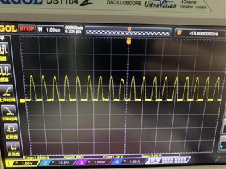
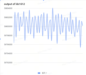
1. When I keep the measuring object and the coil unchanged, the output value of the sensor fluctuates repeatedly within a range, and the fluctuation seems to have certain regularity, not like random noise. What is the reason for the fluctuation? Are there any rules?
2. Use the LDC1612 to measure a moving metal plane and make sure the coil stays above the plane.
(1) What is the difference between measuring in a static state and in a moving state?
(2) If the inductance value of an object is measured in a static state, what is the meaning of the value obtained by measuring a moving object?
looking forward to your answer.
Hello Max,
1. There is some fluctuation expected at the output. Can you check your sensor oscillation amplitude? If the voltage is below 1.2V, the SNR is reduced and could be affecting your output. The app note below discusses this topic and using the correct drive configuration.
https://www.ti.com/lit/an/snoa950/snoa950.pdf
2. When measuring a moving object, you want to make sure that you are measuring at fast enough depending on how quickly your target is moving. Movements in the z axis(axial sensing) will provide better sensitivity generally.
Hello Eddile.
Q1:about the fluctuation.
==> There is some fluctuation expected at the output.
==> Is there experimental data on numerical fluctuations? I need it to judge whether it is normal fluctuations or noise.
1. I fixed the distance between the coil and the measured object as 4.7mm, read the values of the sensor as shown in the table below, and the fluctuation exceeded 8000.(the Coil diameter is 13.1mm and I need check the distance from 3mm to 7mm).
2. the sensor oscillation amplitude as shown in the table bellow.
3. Is there a way to reduce the fluctuation of the value?
Q2:about the sampling time.
I use LDC1612 to measure distance between moving object and coil.
I Setting RCOUNT to 0xFFFF (conversion time 23.6ms), does it mean that I can get a stable distance value after 23.6ms.
If the object is moving at 50mm/s, what should I set the sensor's sampling time to get reliable values?
Looking forward for your reply.
Hi Max,
I ran the LDC1614EVM with a metal target 1cm away. I see much lower variance of about 400 ADC codes.
Your oscillation amplitude scope shot looks like it has a large undershoot(~1V) and very noisy. Can you provide more design details? I have a few requests below.
Schematics
Intended sensor frequency
Are you using internal or external clock?
Max RCOUNT should be set at 0x2000 for 26.2ms conversion time. See the app note below. This means that the conversion is complete after 26.2ms and is ready to read out.
I am checking if we have a tool available to determine sample rate based on speed and size of sensors/target. 50mm/s is not too fast, so I don't see this as an issue though. I will let you know what kind of resources I can find on this.
Hello Eddie.
Q1:
I removed the MSP430 on the LDC1612 EVM board and used STM32 to connect through Dupont lines, and the others remained the same, as shown in the figure below:
In addition, there is a strange place, I use the same register configuration, but the amplitude and frequency of the LDC1612 EVM sensor crystal oscillator are inconsistent with my LDC1612, the following figure shows the information of the LDC1612 EVM:
Below is the information of my LDC1612:
Except that CONFIG(addr 0x1A) needs to be written last, is there any requirement for the writing order of other registers?
My register configuration is as follows:
Q2:
1. Max RCOUNT should be set at 0x2000 for 26.2ms conversion time.
==> I'm using LDC1612 and I didn't find related description in the document snoa944, does this qualification also apply to LDC1612?
2. 50mm/s is not too fast, so I don't see this as an issue though
==> 50mm/s is a minimum value, the actual demand may be greater than 250mm/s.
3. I am checking if we have a tool available to determine sample rate based on speed and size of sensors/target.
==> Looking forward to having such a tool.
Looking forward to your reply, thank you.
Based on your frequency of ~800kHz, it looks like the parallel capacitor is pretty large. This will also reduce your Q factor. I would suggest changing that parallel capacitor to 2200pF. This brings the Q factor from around 10 to 15. This will also bring the frequency up to ~1.2MHz. After changing this capacitor, I also recommend checking your deglitch filter configuration. See Q24 in the FAQ below. You should use the 3.3MHz filter in this configuration.
On the LDC1612, you are correct that this does not have the same limitation of RCOUNT.
Let me know if you are seeing some better stability after making these changes.
Hello Eddie.
Q1: Regarding data fluctuations.
After I changed the shunt capacitor to 3300pf, the ripple went from 3000 to 800, thank you very much for your help.
However, after using a 3300pf capacitor, when I move to the closest distance, the voltage across the coil Vosc will be less than 1.2V, so I have to use 2700pf to ensure that the voltage across Vosc is between 1.2V~1.8V.
is there any other way to increase data stability?
Q2: Regarding the sampling rate.
I need to use LDC1612 to measure the fluctuation of the object (by measuring distance), how to determine the sampling rate of LDC1612?
thank you for your help and looking forward to your reply.
Max,
As mentioned before, also be sure that your glitch filter is set properly.
In regards to the minimum sampling rate, you could determine the amount of time that your target object will be within the range of the coil based on max speed and size of target, then ensure that your sampling rate is fast enough to obtain at least 1 reading in this time. For robustness, it would be best to have a few measurements within the time period.
Hi Eddie.
The Vosc frequency is 1.8MHz, so I set a 3.3MHz filter.
At present, the fluctuation range of the value is still a bit large, which is several times that of the LDC1612 EVM. Is there any error? The following figure is the waveform captured by my Vosc oscilloscope:
In addition, although I only need to use channel 0, in order to use a 40MHz crystal oscillator to obtain higher precision, I refer to Chapter 3.2 of snoa944, using dual channels, and I have two questions for consultation:
1. For channel 1 that is not needed, what do I need to do with IN1A and IN1B, should I ground them?
2. Using this method, will channel 1 interfere with channel 2?
looking forward to your reply.
Max,
I'm looking into these questions and will have recommendations by EOD tooday.
Max,
You could still have higher fluctuations because due to the Q factor. The parallel capacitor could be further reduced to increase Q.
The 40MHz work around discussed in the app note requires that you have a "dummy" sensor on IN1A and IN1B, but ignore the results of this channel. You should set channel 1 for minimum RCOUNT and SETTLECOUNT to minimize the time on this channel. You can also design the "dummy" sensor for faster activation time by designing this sensor with low Q and/or increasing the sensor frequency.
I would not see any additional interference in this configuration. Each channel is activated individually. You would also want to design your "dummy" coil to be very small in size and operate at a higher frequency from the sensing coil. This would reduce activation time and also reduce any possible ringing from the sensing coil.
Hi Eddie:
Can you tell me about the coil on the LDC1612 EVM? Includes Rp, L and C.
I have a question. Because the conversion speed is very fast, INTB will frequently interrupt the MCU. Therefore, I use polling instead of interrupts. The ADC values read twice are inconsistent. I think the ADC values at this time are different. is valid, I'm not sure for the time being if this processing will be problematic.
In addition, I suspect there may be some problems with SETTLECOUNT's Settings. I will check the relevant information further.
We can derive the EVM coil parameters using the LDC calculator tool. The silkscreen shows the coil properties. I have also circled the pertinent parameters that I changed in the tool.
It is possible that your polling timing is incorrect and you are reading the device after it has taken a new measurement. The sensor conversion time is determinstic, therefore you should be able to poll at a fixed rate. If you are using 2 channels, be sure that you are including the activation time and channel switch delay.
Hello.
1. If the value of the data register is read continuously, is it the last value or an unstable value? That is, will LDC1612 update the data register after the conversion?
2. Actually only channel 0 needs to be used, but with dual channels enabled in order to use 40M crystal oscillator, can the IN1A and IN1B pins of channel 1 be grounded or directly connected together? Because I don't have enough room for another coil on my circuit board.
1. The data read will be the last value and the register is updated after conversion.
2. Our documentation only discusses using the 2nd channel with a "dummy" sensor connected. Let me research if this technique is still effective with no "dummy" sensor. I will get back to you with an answer on this.
In general, IN1A and IN1B should be floating if not used. Typically, when using only 1 channel, the unused channel can be left floating as it is grounded internally when inactive.
Max,
Yes, you could still use the 40MHz approach without connecting another coil. In this case, you should leave IN1A and IN1B floating. With no coil connected, you will likely receive conversion errors. You could clear and discard the errors on this channel.
When designing your own hardware, it may be worthwhile to use a 35MHz clock instead of using both channels in order to achieve 40MHz through 2 channels.