This thread has been locked.

If you have a related question, please click the "Ask a related question" button in the top right corner. The newly created question will be automatically linked to this question.

TMAG5170D-Q1: TMAG5170D-Q1 worst case output angle error

Part Number: TMAG5170D-Q1
Other Parts Discussed in Thread: TMAG5170, TMAG5273, TMAG5173-Q1

I would like to ask about calculations for specific case. I cannot find answer according to datasheet nor "TMAG5170 - 2D Angle Error Calculator".

My aplication is angle sensor for automotive. Temperature range -40:85degC. Take the parameters:
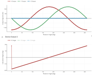
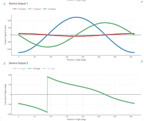
Bx,By peak: 24mT

Input range: 25mT (PTMAG5173A1QDBVRQ1)

CONV_AVG: 011 (8 samples)

Rotation speed: 0.85 Hz

Sampling mode: XYZZYX

X,Y Offset correction: OFF

Channel Gain Attenuation: OFF

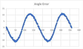
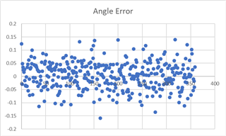
What is the worst-case output angle error in temperature range -40:85degC? 

  • Mateusz,

    We plan to upgrade the 2D angle tool to pull data from our TI Magnetic Sense Simulator tool to allow you to combine simulated results with temperature data with the rotation speed.  This tool is in an early release phase and we will be integrating our full sensor portfolio in the next update.  Right now, the closest option is to use TMAG5273 which is commercial grade, but operates similarly to TMAG5173.

    At a rotation speed of 0.85 Hz (51 RPM), the main sources of error to consider will be from the magnetic field, the input referred noise, quantization, and propogation delay related to the rotation of the magnet.  With the XYZZYX sample pattern and 8x averaging, one conversion will take about 1.225 ms  (6 channels * 8 samples * 25 us + 25 us).  In this time the magnet will rotate about 0.37485 degrees.  Pseudo-simultaneous sampling should produce a result which is roughly at the mid-point of this, so we would be within +/- 0.187 degrees.

    If the sensor is placed along the axis of rotation for the magnet (On-Axis) then we would typically expect fairly well matched amplitude between the X and Y axes and no Z component. As the sensor is moved away from this ideal location, we start to observe more of the vector in the Z-direction and this leads to an imbalance between X and Y.  There are locations off-axis where Z and Y or Z and X will match in amplitude, but in general any imbalance between the axes will lead to angle non-linearity.  Consider the simulation examples below using a peak input magnitude of +/-24 mT:

    On-Axis

    Off-Axis

    It is difficult to estimate the angle error for your particular system without more details about the quality of the input.  However, in the case shown above the two amplitudes are 24 mT and 16 mT.  The resulting maximum angle non-linearity for this case is shown in the next plot

    So with this large mismatch between the two axes, any error related to rotation will be insignificant by comparison.

    To see the effect of input referred noise, we can also look at the error of the On-Axis case with 32x averaging enabled.

    Here we see that the input referred noise from 32x averaging should keep the angle typically within 0.15 degrees.  

    Finally, the output resolution of the TMAG5173-Q1 CORDIC is 1/16 degree, so we would have uncertainty of 0.0625 degrees.

    If we combine the error due to rotation, noise, and quantization, the resulting error is about 0.4 degrees.  However, this does not take into account any error related to device offsets, sensitivity mismatch (which will appear as amplitude mismatch), or actual amplitude mismatch resulting from the position of the sensor.

    As temperature is introduced to the on-axis case, the largest concern will be how well matched the sensitivity drift is between the two axes used for the measurement. Over the full temperature range of the device the drift is specified here

    If we assume the worst case of 1.5% mismatch at our temperature extreme, then our resulting error due to amplitude mismatch comes to:

    Overall, this comes to less than 1 degree total error, assuming the input fields are ideal.

    Thanks,

    Scott