A related question is a question created from another question. When the related question is created, it will be automatically linked to the original question.
If you have a related question, please click the "Ask a related question" button in the top right corner. The newly created question will be automatically linked to this question.
A few questions about the analog part of the design:
1. What are the dimensions of your sensors? 2. What is the physical spacing between your sensors? 3. What are your sensor frequencies? 4. Do the results change for a single channel if all of the other channels are off?
Just so you know, we recommend the FDC1004 over the FDC2xxx devices, especially for liquid-level sensing. The FDC1004 features active shield drivers, which help with EMI management, while many of our customers have struggled with EMC/EMI issues with FDC2xx devices. You can find out more about the FDC1004 at the FDC1004 product folder and on the E2E FDC1004 Frequently Asked Questions age.
The single-channel amplitude data looks like it moves between the values of -4500 to -3500, while the multi-channel measurement ranges from 8000 to 14000. If the two data sets were taken for the same probe and position, it appears the capacitive sensors may be interfering with one-another. You mentioned sensor frequencies of 4.6MHz and 5.1MHz. 1. Are the two frequencies used in alternating probe positions?
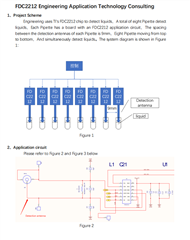
2. The schematic is a little fuzzy, but it seems to show the antenna connected to INxA and the reservoir connected to INxB. What are the details of the INxB connection?
3. What are the Qs of the resonant antennas + PCB inductors for the two frequencies?
4. What is the inductance and self-resonant frequency of your PCB inductor?
The close spacing may be causing mutual interference between your sensors. Placing shields between the sensors may be one option, but the close spacing between the sensor and a shield may affect the sensors and reduce the sensitivity of your system.
A couple of sensor frequencies have been mentioned. Have the design frequencies been confirmed by measurements for a single probe and for multiple active probes? You can easily measure the sensor waveforms with a high impedance oscilloscope probe with a leaded 1k resistor between the probe tip and the sensor test point.
One parameter to consider is the inductor's self-resonant frequency (SRF), where the inductor self-resonates. Above this frequency, it stops acting like an inductor and starts acting like a capacitor. If your sensor operate frequency is more than 70%-80% of the self-resonant frequency, then it will not work reliably. Since you have said a single probe seems to work okay, this may not be the root cause, but it is something to consider, especially considering item (2) above.