This thread has been locked.

If you have a related question, please click the "Ask a related question" button in the top right corner. The newly created question will be automatically linked to this question.

DRV421: ER PIN setting during demagnetization

Part Number: DRV421

Hello All

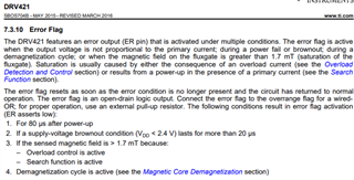
- We are working with DRV421. Looking to the user manual, ER asserts low when having a demagnetization cycle.

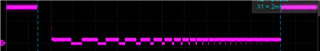
- We have performed some measurement monitoring OR and ER pin. In the below scope screenshot, in yellow is OR pin which is changing during demagnetization.

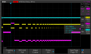
>> But when looking to ER pin it is always set to high.

[Question]

Is the statement in the user manual of DRV421 (ER asserts low during demagnetization) is applicable always when doing demagnetization ?

(Or it is a possibility but does not happen all the time and can explain what we measured)

In advance thank you for any support,

  • Hello Stephane,

    I would assume that the datasheet is correct but I will attempt to see in the lab tomorrow.  Do you use a large Rshunt?  How does Vout look during this?

    Regards,

    Javier

  • Hello,

    Thank you for you reply,

    "Do you use a large Rshunt?"

    Yes we are using a large Rshunt about 100ko.

    "How does Vout look during this?"

    Actually is what can be seen in purple in the scope previous scope screenshot.

    In advance thank you for your reply and support,

    Best Regards,

  • Hello Stephane,

    Using a large Rshunt will not allow for the Demag to work correctly.  I verified you are correct that the ER flag is not correct.  I believe the correct way the device should have been worded is if the demag function casuses the core to saturate and apply a large field on the  DRV421 the ER flag with initiate.

    I have some information but measuring small currents is rather difficult and challenging with he DRV421.  

    See these post for more information.  The first one has links to others.

    https://e2e.ti.com/support/sensors-group/sensors/f/sensors-forum/1019111/drv421-residual-current-detector-application-regarding-the-fluxgate-sensor-front-end-offset

    https://e2e.ti.com/support/sensors-group/sensors/f/sensors-forum/941265/drv421-doubts-and-questions-regarding-feasibility-of-rcd-residual-current-detector-design-with-drv421-ic

  • Hello Javier,

    Thank you for your feedback and the test,

    Regarding on what you have pointed out "measuring small currents is rather difficult". We are still going through the links you have previously mentioned, we have some additional questions

    1- We use the DRV421 spreadsheet to do our setting (no NOK were thrown). 

    >> The fact that measuring small current (putting a large Rshunt) was not raised as not possible. Do we misconfigure the setting on the spreadheets?

    2- Regarding the difficulties to do the demagnetization, in the spreadsheet there are some below errors mentionned:

    >> Is the "Sensor Offset (no demagnetization)", an other offset error (other than the one due to the magnetization) ?

    (Meaning in small current we could have the offset due the demagnetization + the Fluxgate Offset Error?)

    In advance thank you for you support

  • Hello Stephane,

    >> The fact that measuring small current (putting a large Rshunt) was not raised as not possible. Do we misconfigure the setting on the spreadheets?

    This is correct but this does have to due with external issues like the magnetic core magnetization and the DRV421 offset and the amount of external field getting coupled into the air gap where the DRV421 is coupling magnetically.  The calculator is just an aid with math calculations.

    Is the "Sensor Offset (no demagnetization)", an other offset error (other than the one due to the magnetization) ?

    There are a few offsets that come into play.  The magnetic core, not everything is removed with degauss and depends on the core material and design.  With large resistance the degauss will not work.  External field getting coupled to the airgap.   Offset of the DRV421.

  • Hello,

    Thank you feedback,

    1- Actually for the question about "Sensor Offset (no demagnetization)" from the speadsheet, we wanted to know where this offset is applied.

    >> Would it be possible give more details about this offset "Sensor Offset (no demagnetization)"?


    2 - Regarding the ER PIN we also noticed that we have permanent error raised by the ER pin. We checked for the below use cases (1-)(2-)(3-)(4-)

    We are over the (1-) power-up start up, we checked for (2 -)supply-voltage (VDD is OK),  we  tested removing the (3-) magnetic core, we tested without starting any  (4-) demagnetization. (No primary current)


    We still observed ER pin set permanently to low .

    (Note: when having a primary current, we still see Vout changing as if compensation coil current was applied regardless the fact that the ER pin is set to low)

    >> Besides the above use cases having ER pin sets to low, is there any other use case/condition which lead having ER pin set to low?

    In advance thank you for your support,

  • Hello Stephane,

    >> Would it be possible give more details about this offset "Sensor Offset (no demagnetization)"?

    With only the DRV421 and ignoring the magnetization of the core the offset is 8µT.  You then multiply by the gain of your core to get the error you would expect.  For example  DRV421 Offset.  Offset = 8µT, Core Gain 600µT/A;  Offset error = 8µT/(600µT/A)= 13.3mA (error due to offset).  Not sure what the 11.4mA was calculated above but it is very similar.

    >> Besides the above use cases having ER pin sets to low, is there any other use case/condition which lead having ER pin set to low?

    In advance thank you for your support,

    Please verify with a lower resistance you can meet the requirements.  With 100kΩ your max compensation current is about 50µA, this is an estimate as you need to include other impedances and I assume the h-bride could drive to 5V which it cannot.  Based on your Turns above of 1200 you will only compensate to 60mA.  If it cannot compensate the field seen at the at then you will get an error.  It is most likely you would get an OR flag as the differential amplifier would be over range.  

    Regards,

    Javier

  • Hello,

    Thank you for your feedback,

    For the second topic we checked also the OR pin and it is HIGH whereas the ER pin is permanently LOW. Regardless on this ER pin, VOUT still reacting on primary current.

    We are still looking at it.