This thread has been locked.

If you have a related question, please click the "Ask a related question" button in the top right corner. The newly created question will be automatically linked to this question.

TMP1075: GND plane connection

Part Number: TMP1075

Hello team,

We are using your recommended TMP1075DSGR temperature sensors to measure the temperature of our power stage (half bridge - 2kW peak - 50V nom)
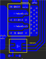
To be more precise, we connect the source of the power transistor of the half bridge to the central pin of your sensor.

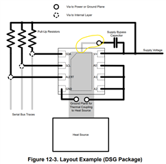
As shown in your datasheet.

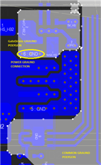
However, we're using land polygon separation. For example, the power ground is connected to the driver winter at one point, and the driver ground is also connected to the common ground at one point, in order to eliminate the flow of power currents, which can reach 35A DC and have a significant variable component.

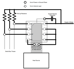
Your datasheet shows the connection of the heat source and probably the signal ground at one point - as shown in the figure.

We are a bit worried as to whether this connection will cause pulse noise transmission from the power ground to the digital (low-current/common) ground. Including interfering with data transmission via I2C.

However, it seems dangerous not to connect the heat source and the digital ground - will we damage the sensor in this case?

Could you please specify for us which way you consider to be the best way.

Also could you please explain how best to connect pin GND and pin A2 to the ground polygon - heat source. Thin connections as in the datasheet or it is possible to connect by polygon as shown in our layout and whether there is a fundamental difference.

Thanks and best regards,

Michael

  • Hello Michael,

    Thank you for posting this concern. As long as the copper pad remains under the TMP1075, not extending it will not harm the device. This could lead to greater temperature error but will not harm the device. What exactly is your heat source? Can you give more details?

    Best Regards,

    Meredith McKean

  • Hi Meredith,

    thanks for your answer.

    The main heat source are the power FETs in the system. There are in total six of them, 3 half bridges to create AC current from the DC current source for the e-motor.

    Best regards,

    Michael 

  • Hi Meredith,

    one follow up question:

    By not extending the copper, you mean connecting the thermal pad to PGND and reference all other pins to SGND, correct?
    So the thermal pad and the ground supply are not internally connected?
    The concern would be, that the temperature sensor not only covers the thermal pad, but also all other leads, which are connected to the cooler signal ground, correct?

    As mentioned, GaN FETs are being used, which are the main heat source in our system. We would like to use those temperature sensors to monitor the junction temperature of the FETs. 
    Naturally, the closer we can get to the actual temperature, the better. Do you have some recommendations for us on how we could improve our measurement?

    Best regards,

    Michael

  • Hi Michael,

    What Meredith meant was that the thermal pad should be connected to SGND along with the other grounded pins on the TMP1075, but not extending the thermal pad copper to reach PGND which could introduce the noise transients you are worried about to the TMP1075. This will not be an optimal layout, and goes the against the layout recommendations in the datasheet, but it will protect the TMP1075.

    Alternatively, our product line has just APL'ed a new isolated temp sensor, ISOTMP35. This is an analog temp sensor, but it has basic level isolation and is designed to directly connect to high voltage temperature sources like GaN FETs. If you are still in the development phase, you may want to consider this device for this application.

    Thanks

    -Alex Thompson