This thread has been locked.

If you have a related question, please click the "Ask a related question" button in the top right corner. The newly created question will be automatically linked to this question.

DRV5055: Magnet Selection

Part Number: DRV5055
Other Parts Discussed in Thread: TMAG5273,

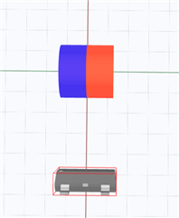
My team and I are designing for an application where we need to measure the angle of a rotating magnet placed above the sensor. The magnet rotates +/-40 degrees from its rest position about the y-axis (with respect to the sensor measuring the z-axis). After reading through the AN on Hall effect sensor angle measurement, we believe the "One Bipolar Sensor, Lookup Table Calibrated" method would best suit our application. The limited rotational range of the magnet prevents us from measuring the magnetic peaks. We also cannot place the sensor on-axis with the magnet due to mechanical constraints, preventing us from using a multi-axis sensor like the TMAG5273 without calibration, which we cannot reliably calibrate due to the limited rotational range. We can measure the +40 degree, -40 degree and 0 degree angles in our application, so we can at best perform a linear calibration.

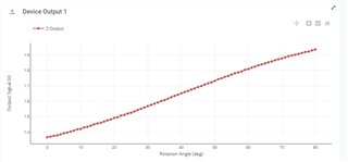
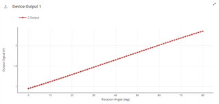
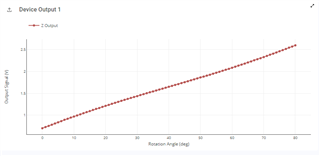
My question is what magnet shape is best suited for this type of application to achieve the most linear results. The AN suggests a diametrically magnetized ring or cylinder. Given our constraint on the magnet being about the y-axis, I've drafted an axial cylinder and a diametric ring using TIMSS. I noticed the axial cylinder appears exhibit more linearity than the diametric ring across the 80 degree rotation. Is there other options I should consider? I don't fully understand how the magnet shape, magnetization pattern, and geometry have on the linearity of the measured output.


Let me know if there is more detail I can provide.

Thanks,

Jeff

  • Jeff,

    If I understand your setup correctly, you are placing the ring magnet on your rotating shaft, and wanting to measure +/- 40 degrees with this magnet.  I believe you may have TIMSS rotating the magnet differently than you expect.  If you are in the "rotation" setting in TIMSS the rotation occurs about the Z axis.  To setup rotation about Y, you could place the magnet on the origin and use the joystick setting to ensure the rotation is in the correct direction.  You can confirm using the animations provided after simulating.

    I have a sample rotation setup in the .json below using the diametric magnet.  Save the code locally and then use the import function to view the results:

    4Layer Example.json
    {
      "version": "3.1.3",
      "design_name": "",
      "magnet_id": 4,
      "poles": 2,
      "material_id": 1,
      "grade_id": 1,
      "select_remanence": "br_average",
      "remanence": 1200,
      "temperature": 20,
      "temperature_coefficient": -0.12,
      "coercivity": 10.9,
      "function_id": 3,
      "magnet_geometry": {
        "outer_diameter": 5,
        "inner_diameter": 3,
        "height": 6
      },
      "magnet_position": {
        "x_position": 0,
        "y_position": 0,
        "z_position": 0
      },
      "magnet_angle": {
        "x_angle": 90,
        "y_angle": -45,
        "z_angle": 0
      },
      "magnet_movement": {
        "tilt_angle": 80,
        "xy_angle": 0
      },
      "sim_setting": {
        "tilt_angle_step_size": 1
      },
      "sensor": [
        {
          "sensor_id": "DRV5055",
          "sensor_position": {
            "x_position": 5,
            "y_position": 0,
            "z_position": 0
          },
          "sensor_angle": {
            "x_angle": 0,
            "y_angle": -90,
            "z_angle": 0
          },
          "custom_inputs": {
            "variant": "DRV5055Z3QDBZR",
            "applied_vcc": 3.3
          },
          "id": -1
        }
      ]
    }

    An axially magnetized ring magnet as you have pictured above will have radial symmetry and therefore we would expect no change in the magnetic field, which would not be of any use to you.  The diametric magnet is a good choice.   From this example simulation, +/- 40 degrees looks like it will work quite well.  The result isn't perfectly linear on the output since the field will be sinusoidal during this rotation, but you can align the magnet to the most linear portion of the curve.  If you can afford an arcsin calculation in the MCU then you should be able to linearize the result further.

    Thanks,

    Scott

  • I think there is a misunderstanding on the rotation. I've attached the JSON configurations of the two designs that I came up with. I'd like to better understand if these are the two designs that I should consider, and if so, what parameters will maximize linearity.


    Cylinder:

    {
      "version": "3.1.3",
      "design_name": "DRV5055 Cylinder",
      "magnet_id": 3,
      "poles": 2,
      "material_id": 1,
      "grade_id": 1,
      "select_remanence": "br_average",
      "remanence": 1200,
      "temperature": 20,
      "temperature_coefficient": -0.12,
      "coercivity": 10.9,
      "function_id": 4,
      "magnet_geometry": {
        "outer_diameter": 2.56,
        "height": 2.56
      },
      "magnet_position": {
        "x_position": 0,
        "y_position": 0,
        "z_position": 0
      },
      "magnet_angle": {
        "x_angle": 270,
        "y_angle": 0,
        "z_angle": -40
      },
      "magnet_movement": {
        "arc_length": 80
      },
      "sim_setting": {
        "angular_step_size": 1
      },
      "sensor": [
        {
          "id": 9602,
          "custom_inputs": {
            "variant": "DRV5055A1QDBZR",
            "applied_vcc": 3.3,
            "bop": "bop_typ",
            "brp": "brp_typ",
            "temperature_compensation": 0,
            "averaging": 0,
            "maximum_input": 0
          },
          "sensor_position": {
            "x_position": 5.8,
            "y_position": 0,
            "z_position": 0
          },
          "sensor_angle": {
            "x_angle": 90,
            "y_angle": 90,
            "z_angle": 270
          },
          "user_design": 11782,
          "sensor_id": "DRV5055"
        }
      ]
    }


    Ring:

    {
      "version": "3.1.3",
      "design_name": "DRV5055 Ring",
      "magnet_id": 4,
      "poles": 2,
      "material_id": 7,
      "grade_id": 1,
      "select_remanence": "br_average",
      "remanence": 600,
      "temperature": 20,
      "temperature_coefficient": -0.12,
      "coercivity": 10.9,
      "function_id": 4,
      "magnet_geometry": {
        "outer_diameter": 5,
        "inner_diameter": 2,
        "height": 1
      },
      "magnet_position": {
        "x_position": 0,
        "y_position": 0,
        "z_position": 0
      },
      "magnet_angle": {
        "x_angle": 0,
        "y_angle": 0,
        "z_angle": 45
      },
      "magnet_movement": {
        "arc_length": -90
      },
      "sim_setting": {
        "angular_step_size": 1
      },
      "sensor": [
        {
          "id": 9612,
          "custom_inputs": {
            "variant": "DRV5055A1QDBZR",
            "applied_vcc": 3.3,
            "bop": "bop_typ",
            "brp": "brp_typ",
            "temperature_compensation": 0,
            "averaging": 0,
            "maximum_input": 0
          },
          "sensor_position": {
            "x_position": 5.8,
            "y_position": 0,
            "z_position": 0
          },
          "sensor_angle": {
            "x_angle": 90,
            "y_angle": 90,
            "z_angle": 270
          },
          "user_design": 11881,
          "sensor_id": "DRV5055"
        }
      ]
    }

  • Jeff,

    Thanks for sharing your .json files.  It does look like in your case that the axial magnet will work with the DRV5055.  I exported the data from each simulation to .csv through the menu in the top right.  I calculated the change in Bz and the change in calculated angle from point to point and in both cases, the linearity of this calculation looks a little flatter.  

    Since the input with a ring magnet better resembles the zero crossing region of a sine wave, the derivative of this should resemble the peak region of a cosine wave, and this is what we observe.

    For contrast, I also normalized the By and Bz field components and took the arctangent to demonstrate the possible linearity with a 3D sensor like TMAG5273. Even if the calibration is estimated here, it might be possible to produce a more linear result than either method with the 1D sensor.  You can adjust the "Y Gain Factor" for either magnet to see the impact of error from this calibration method.

    4Layer_Report.xlsx

    As far as the behavior of the axial magnet, the linear region we observe as the magnet tilts will be governed by the length of the magnet, but if the magnet gets too long then we create distortion when the ends of the magnet get closer to the magnet. See below for a comparison of different lengths. Your selected length looks near optimal.

    1mm

    2.56mm

    3.75mm

    6mm

    Thanks,

    Scott