This thread has been locked.

If you have a related question, please click the "Ask a related question" button in the top right corner. The newly created question will be automatically linked to this question.

Amplifiers forum

Part Number: PGA308EVM
Other Parts Discussed in Thread: PGA308

Tool/software:

Customer called in, downloaded the sboc257b and sboc256b software for the usbdeck platform but it's not working properly. We're running both windows 10 and 11. 


Ref:MSG20307479_OjH6YgrM2UecbRAz34T

Dear John Garcia,

Good day.

Thank you for contacting TI Customer Support and choosing TI Product for your project.

Regarding your inquiry, I checked our past customers' issues with this EVM and I suggest that you check the e2e thread below.

Link: https://e2e.ti.com/support/amplifiers-group/amplifiers/f/amplifiers-forum/854907/compiler-pga308evm-evm-in-windows-7-or-windows-10-driver-issues/3161558#3161558

This is supported by one of our experts in e2e and hopefully, this works on your end.

I hope my answer resolves your query. I would appreciate it if you could click the "Accept Solution" on case number CS2398245 on your TI Customer Support Portal to close this case on your end formally. 

If any clarification particular to this request is needed, please reply to this email within the next 5 days and let me know before the case is closed by the system.

To help us improve our services, we would like to hear your feedback in a quick survey once your query is resolved.

Kind Regards,

Renan Adriano
Texas Instruments | Customer Support


From: John Garcia
Sent: Monday, June 10, 2024 4:28 PM
To: TI Customer Support <support@ti.com>
Subject: RE: CS2398245: myTI account assistance


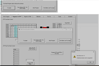
The 308 software does not work now .


From: John Garcia
Sent: Tuesday, June 11, 2024 7:30 AM
To: TI Customer Support <support@ti.com>
Subject: RE: CS2398245: myTI account assistance


From: TI Customer Support <support@ti.com>
Sent: Monday, June 10, 2024 4:57 PM
To: John Garcia <john.garcia@ihydrant.com>
Subject: RE: CS2398245: myTI account assistance


ATTENTION: This email came from an EXTERNAL SENDER and should be CHECKED CAREFULLY BEFORE OPENING!


Hello John,

Good day.

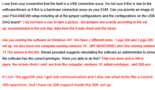
Can you provide more details on your issue? A screenshot/photo, error message, or anything that can help us further see your issue will help a lot.

The information you provided is very limited and I having a hard time to pin point which possible solution to offer. 

By the way do you have a valid myTi account?

Looking forward to your response.

Kind Regards,

Renan Adriano
Texas Instruments | Customer Support

after installing a new  usb driver . the usb daq runs as a pga 309 , but does not run the pga 308 applications it fails as above .

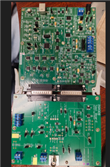
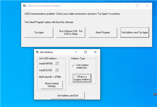
the next set of questions involve once  we get the system up and active , what are the jmpr settings as well as connector  to hook up the 1 wire to an external packaged device with vdd, vss and output  to be able to communicate and read fault or current status  of the device ( packaged ) 

  • Hi John,

    I see from your screenshot that the fault is a USB connection issue. I'm not sure if this is due to the software/drivers or if this is a hardware connection issue on your EVM. Can you provide an image of your PGA308EVM setup including all of the jumper configurations and the configurations on the USB-DAQ board?

    Are you running the software on Windows 10? The advice in the link Renan provided suggests reinstalling the software as administrator to ensure the software has the correct privileges. Were you able to do this?

    Thanks,

    Zach 

  • Hi John,

    1.) As you are unable to provide an image of your jumper configuration, can you confirm the exact datasheet image you are following to set up your jumper configuration? For example: PGAEVM User's Guide (SBOU060A) figure 3-5.

    2.) From my understanding you are running the PGA308.exe software on Windows 10 and are receiving the error. When you run the PGA309EVM software on the same windows 10 computer you are successful.

    Are you using the same USB-DAQ controller for both PGA308EVM and PGA309EVM? Or are you using two different USB-DAQ controllers, one for each EVM?

    If you select the "Run without USB" option on the PGA308EVM are you able to preview the GUI?

    Thanks,

    Zach

  • A Message from the TI E2ETm design support forums


    Dear E2E User:

    Per the ongoing discussion on E2E, an answer was suggested to resolve your issue.

    Please let us know if you believe the issue has been resolved. Please click one of the following buttons on the thread:

    1: If the answer provided resolved your issue, click This resolved my issue

    2: If the answer provided did not resolve your issue, and your question needs further attention, click This did NOT resolve my issue

    This thread will be locked after 30 days of inactivity.

    Regards,
    E2E team
    E2E.ti.com

    RE: Amplifiers forum


    Zach Olson

    Hi John,

    1. As you are unable to provide an image of your jumper configuration, can you confirm the exact datasheet image you are following to set up your jumper configuration? For example: PGAEVM User's Guide (SBOU060A) figure 3-5.

    I had a compatriot take a snap shot of the evm it is attached.

    2.) From my understanding you are running the PGA308.exe software on Windows 10 and are receiving the error. When you run the PGA309EVM software on the same windows 10 computer you are successful.

    Are you using the same USB-DAQ controller for both PGA308EVM and PGA309EVM? Or are you using two different USB-DAQ controllers, one for each EVM? Separate  usb -daq controllersOne for each EVM

    If you select the "Run without USB" option on the PGA308EVM are you able to preview the GUI sometimes .

    Thanks,

    Zach


    View online


    You received this notification because you subscribed to the forum.  To unsubscribe from only this thread, go here.

    Flag this post as spam/abuse.

  • Hi John,

    Thanks for providing the image of your board configuration.

    When you connect this USB-DAQ board to the 6-9V power supply, are you able to see the 3 LEDs in the bottom left of the board light up? These LEDs are labelled "μC OK", "3.3V", and "Vcc".

    I understand you are using two separate USB-DAQ controllers, one for each EVM. As you have successfully connected using the PGA309EVM and its accompanying USB-DAQ controller I will refer to this USB-DAQ as "known good". The USB-DAQ you currently have connected to your PGA308EVM will be referred to as "in question".

    You can attempt an A-B-A swap by connecting the known-good USB-DAQ controller to the PGA308EVM board and the USB-DAQ in question to the PGA309EVM.

    As you are connecting the EVMs, ensure that the power supply cable is connected and powered on before the USB cable is connected. You may also do an A-B-A swap with the USB cable to ensure the cable is good as well.

    Thanks,

    Zach

  • all the Leds  uc/ok, 3.3v Vcc, vdut  are all lit..Switching USB daq boards makes no difference   the issue follows the 308 board as well as running the 308.exe program. 

    I have followed the connection scheme of power,  then usb then load the program. I have swapped out the cables both with a new cable and between the 2 evms on the same computer as well as to both computers. 

    John Garcia 

  • Hi John,

    I understand both USB-DAQ boards are working correctly and the issue is only present when connecting with the PGA308EVM.

    When you run the PGA308.exe program, does the "Vdut" LED light up?

    In my testing, the PGA308EVM software will run and light up the Vdut LED as long as the USB is connected to the USB-DAQ, even if the PGA308EVM is not connected to the USB-DAQ.

    Are you able to select "Set Address and Try Again"? If so, please ensure that the USB address aligns with your jumper configuration (JUMP4 and JUMP5).

    Regards,

    Zach

  •  i get   a time out  and an error insufficient memory.

  • Hi John,

    When you run the PGA308.exe program, does the "Vdut" LED light up?

    Regards,

    Zach

  • yes, it comes on.

    my primary use case , is to be able to read and debug sensors  that are complete using the 1 wire interface. how to do this is not well detailed in any of the documents.

    jg

  • Hi John,

    The VDUT light should only come on if the software is communicating. I see in the previous comments that you noticed this behavior after installing a new USB driver.

    Was the PGA308EVM software operating correctly before the new USB driver was installed?

    Are you able to try on another computer that did not install this USB driver?

    You can also try probing the 1W pin on the PGA308EVM while stating the software to determine if the one-wire is attempting to communicate with the device. Note the PGA308 has a finite number of OTP banks, so if the all OTP was already written sometimes the EVM can appear dead. If necessary we should be able to sample another PGA308EVM to be sure the issue is not hardware related.

    The one-wire protocol, timing diagrams, register configurations, and operating modes are detailed exhaustively in the PGA308 User's Guide: https://www.ti.com/lit/ug/sbou069b/sbou069b.pdf 

    Regards,

    Zach

  • I reviewed all the documents on the pga 308 test board including your link. to documents 

    There are no recommendations nor notations of the jumper setting nor the Terminal connections to connect an external fully packaged production sensor  for the one wire communications . 

    All references pictures have only the 3 or 4 wire connections shown in a generic form with no indications of terminals on the pga308 test board nor what if any jmprs have to be configured to get the 1 wire interface as well as the power and ground to a set of terminals . on the pga 308 test board there are jumprs jmp7 and jumper jmp1 , jmpr 6 ,3 , 11 that all could influence the connections but there is no reference to these in the 308 documents. nor in the 1 wire sections.

    what are the jumper settings for an external device as well as what terminal blocks or ports are connected to the external packaged sensor to acess the 1 wie interface?

    jg

  • Hi John,

    Here is the detailed schematic for the PGA308EVM. This should help provide insight to all your jumper configuration questions.

    PGA308EVM Schematic.pdf

    You can connect you sensor's analog output to terminal T5 and set jumpers 9, 10. 17, 18 to the "EXT" and "NC" positions.

    Use jumper 1 and jumper 7 to configure your device in 3-wire or 4-wire mode, depending on your requirements.

    If using 4-wire mode, the 1W pin can be accessed directly using the PRG test point on the PGA308EVM.

    I hope this helps. Please let me know if you have additional questions about the PGA308EVM jumper configurations.

    Regards,

    Zach

  • i am a bit confused: my sensor contains a bridge with temperature compensation , and a pga 308 circuit card. it has a vcc in,  a gnd pin and a sensor vout pin

     based on the jumpers , which wire from my packaged device goes where? since t5 is connected directly into the 308 input  based on 17 and 18 , and 9 and 10

    where  do i get vcc from for my full sensor and  do i put the output to which pin on t5 , and the other gnd to what location?

    jg

  • Hi John,

    my sensor contains a bridge with temperature compensation , and a pga 308 circuit card. it has a vcc in,  a gnd pin and a sensor vout pin

    It sounds like your sensor already has a PGA308 device onboard. You would need to connect a VCC supply and GND potential to power on the device. As your sensor only provides the Vout pin, I would assume the PGA308 is configured in 3-wire mode.

    Maybe it will help clear things up if you can provide a block diagram showing your system and what you are trying to accomplish with your sensor and the PGA308EVM?

    Can you also provide a schematic of your sensor and PGA308 circuit card?

    Thanks,

    Zach

  • the packaged sensor is a custom produced device for Ihydrant.  We have been seeing devices come back from the field that behave abnormally.

    the behavior appears to be consistent with various failure modes or possibly memory/programming issues in the pga308 in the device.

    Since the sensors are produced by a 3rd party for us, we are trying to narrow down the type of failure without deconstruction of the device which would void any return and replacement of the packaged sensor.  I am looking for cracked or damaged Bridge devices, damaged temperature compensation resistors in the bridge, Evidence of the 308 memories being scrambled by possible abnormal pulse feedback on the output/program line.

    Looking to see if either over-range or under-range default voltages are being activated inside the 308 in the total sensor. 

    Looking to understand if the 308 device is damaged and has no communication since some devices have output voltages that track the vcc , and others are stuck at either vcc or 0 pressure output voltage (.1 volt) regardless of what pressure is applied to the pressure port of the device.

    The device is configured  just like your schematic    with the temperature compensation resistor, and an internal regulator set at 2.7volts. the lower limit is 0.1volt dc for atmospheric, and 2.1 volts for 500 psi (4mv per psi)

    none of this is document nor provisioned on the evm .

    Based on that  we have a +3volt in wire a sensor out wire and a gnd wire ,

     would it not make sense that,  jmpr 13  to nc

    jmpr 10 nc , jmpr 1 to nc,  jmpr 7  vout to one , jmpr 5 remove

    remove r20 on the 308test board  also  there needs to be a disconnect somehow to the line to VFb on the 308chip on the test board.(cut lead?)

    My sensor then should connect to t4 vout to sensor out, gnd to gnd  , and a jumper clip from test point vs to my sensor vcc.

    jg 

  • Hi John,

    Thanks for the additional background. The PGA308EVM is a designed to evaluate the performance of a typical PGA308 device, or more specifically, the sample PGA308 device that is populated on the EVM. This tool is commonly used during the design cycle to evaluate the device in a typical application circuit. Sometimes it is also be used as a correlation test to compare the operation of a known-good device (PGA308EVM) with the operation of a failed unit such as your sensor.

    Based on your description, I don't think you need the PGA308EVM to interface with your sensor. You simply will need to communicate with the PGA308 on-board your sensor assembly as it is configured. I suggest reading about the 3-wire mode in the PGA308 User's guide, especially section 5.6 1W Connected to Vout Program Mode, Virtual Software Lock Mode.

    I also suggest reading about the internal fault monitors in the PGA308 User's Guide: see section 2.5, figure 3-12, and figure 3-16. Also refer to the register configurations near the end of the guide to understand how the fault flags are configured.

    Sections 4.4-4.6 describes the 1W digital interface and timing. Figure 5-8 shows the block diagram for 1W read mode.

    https://www.ti.com/lit/ug/sbou069b/sbou069b.pdf 

    I hope this helps.

    Regards,

    Zach