Other Parts Discussed in Thread: DCA1000EVM, AWR2944, AWR2243, AWR1642
Tool/software:
Hi Experts,
Asking your guidance on this query from cx:
I am working on getting AWR1843 data using DCA1000 EVM.
I got the data, but I am unable to understand the config used for getting this data.
I have doubts regarding understanding the config data uploaded while getting data from DCA1000EVM and AWR1843
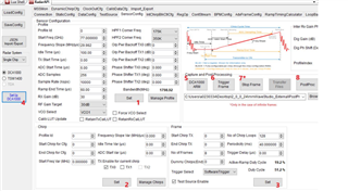
1) How to select two azimuth antennas? Which of Tx0,Tx1,Tx2 are azimuth antennas for AWR1843
2) Should the 'Format' in ADC config be 'complex2x' or 'complex1x' for 2 bytes for real and 2 bytes for imaginary representation
3) the downloaded config file is in .xml format. I am unable to understand it. How to download the config file .cfg format like ike as given in 'profile_2d.cfg' in folder "C:\ti\mmwave_sdk_03_06_00_00-LTS\packages\ti\demo\xwr18xx\mmw\profiles"
4) The saved manage chirp sscreenshot only Tx1 enable, with chirp start index,chirp end index =0, what about other transmitter which was enabled?
So finally, these are the screenshots and the questions I need resolving:
Thank you for your assistance.
Regards,
Archie A.
Sharing these links to make understand the questions. These are the links: