AWR2944EVM: Can't access/activate G15 for FRAME_START PINMUX signal

Part Number: AWR2944EVM

Tool/software:

Hello,

On the AWR2944EVM, I have been trying to activate the G15 FRAME_START signal (mode 13) with the following code in the mssgenerated ti_pinmux_config.c, after reading a very similar E2E post to this. I am working with the OOB TDM demo. PIN_PULL_DIRECTION seems to no longer exist anymore so I replaced it with PIN_PULL_DOWN.

{
    PIN_PAD_AZ,
    ( PIN_MODE(13) | ( PIN_PULL_DISABLE & PIN_PULL_DOWN) )
},

I then regenerate the binaries using gmake mmwDemoTDM, having slightly modified it so that the syscfg files are not regenerated.

I would expect the D6 LED to light up on every frame start, since D6 is connected to MSS_GPIO_2, which is the ball name of G15. However, the LED does not light up at all and no signal shows up on the oscilloscope either.

1. What am I doing wrong? Do I need to modify/add more code?

2. Is the solder around the D6 LED not the right place to measure from? If not, where should I measure from?

3. For alternatives, I have tried looking for the R15 and T17 pads, but they weren't exposed on my unmodified AWR2944EVM or I couldn't find them. It would be great if you could point me toward them.

Thank you!

Best,

Aaron

  • Hello,

    Yes, you should see the LED toggle when the frames are triggering if enabled properly. Most likely this is a software issue and not a hardware issue. I will loop in our software team.

    Regards,

    Adrian

  • Hi Adrian and software team,

    Upon adding FORCE_OUTPUT_ENABLE to that line of code, I observed very small impulse-like pulses on the oscilloscope. There was a ton of noise (could be interference from parts/TX radiation very nearby?) and the LED didn't turn on, likely due to the fact that the peaks were a mere 200 mV and had no pulse width (like I said, impulses). 

    I am decently sure that this was the correct signal, as I tried chirp_start and frame_start. For the first, observed four successive tiny peaks at 200 us separation and 1 second burst intervals (as I had configured). For the second, I observed the same tiny impulses that barely rose above a considerable quantity of noise at 10 ms intervals, consistent with the separate configuration I had set up for it.

    So the timing seems right but the signals are really weak.

    1. I am accessing G15 directly below the LED. Is that the recommended spot to solder something on? Would removing the LED help?

    2. Are there any other ways to increase the pulse height and width? 

    3. Is there a way to access R15 or T17?

    4. Have you or any of your team members tested the FRAME_START signal on your bench and observed the LED flickering for each frame?

    Also, please let me know if anything is wrong with my software configuration.

    Thanks,

    Aaron

  • Hi,

    Our demos do not make use of this configuration. 

    Have you or any of your team members tested the FRAME_START signal on your bench and observed the LED flickering for each frame?

    I will ask the HW team to comment on the other questions

    thank you

    Cesar

  • Hello,

    We have not tried this before on the EVM. Let me check with the firmware team on the behavior of FRAME_START. It is possible that this signal will only toggle for a short period (i.e. 50ns or so) and thus will be too fast to see the LED toggle.

    What is the bandwidth of the scope you are using?

    Regards,

    Adrian

  • Hi Adrian,

    I am using a Siglent SDS 1202X-E oscilloscope with 200 MHz bandwidth.

    Best,

    Aaron

  • Hello Aaron,

    Sorry for the delay. This scope should be sufficient to see the frame_start signal. We need to test this on our end to confirm. I will work with Cesar to get a software build prepared to verify on our end.

    Also, if you have a compiled appimage you can send it to me and I can check it on my board.

    Regards,

    Adrian

  • I have tried to attach it here, but not sure if it worked. Could you send me your email so the attachment goes through? Thanks.

  • Hello,

    This link is blocked on the TI network but I can try to download it when I get home. If that does not work I will send you a drive link to upload.

    Regards,

    Adrian

  • Perhaps a DropBox link will go through: https://www.dropbox.com/scl/fi/xb5sru25cj9pmuvxzivw2/awr2944_mmw_demoTDM.appimage?rlkey=1leutx8bdh4vqdckkd9r3ia48&st=c0jd8r0o&dl=0

    Turns out the website deleted the file after I tested the link. Here's another one if you want the xer5f and xe66 binaries for CCS too.

    https://file.io/2A3jfyv1ogHA

    To be specific about my change: it is basically stock mmwDemo with ti_pinmux_config.c in the mssgenerated folder having the following

    inserted in gPinMuxMainDomainCfg[]

    {
        PIN_PAD_AZ,
        ( PIN_MODE(13) | PIN_PULL_DISABLE | PIN_FORCE_OUTPUT_ENABLE )
    },
  • Hi aozer,

    Let me know if the code works on your end.

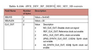
    Can A11 - OSC_CLKTOP also publish the frame start signal? It looks like its periodicity matches that of the frame periodicity. It's about 1.06V, so if it can be used, that would be great.

    However, according to the AWR2944EVM datasheet, it is the "Reference clock output from clocking subsystem
    after cleanup PLL." Could you clarify what that means?

    Thanks,

    Aaron

  • Hello,

    Yes, I was able to download it. I will test tomorrow and let you know the result.

    The OSC_CLKOUT should not be matching the frame periodicity. You can configure the following outputs.

    1. 40MHz reference clock

    2. 1.8GHz divided down APLL

    3. 2.5GHz divided down synthesizer clock

    4. 5GHz divided down synthesizer clock

    Regards,

    Adrian