This thread has been locked.

If you have a related question, please click the "Ask a related question" button in the top right corner. The newly created question will be automatically linked to this question.

IWRL6432BOOST: IWRL6432BOOST ADC data acquisition procedure via SPI

Part Number: IWRL6432BOOST
Other Parts Discussed in Thread: MMWAVE-L-SDK, IWRL6432AOP, IWRL6432

Tool/software:

Hi expert,

I am planning to use IWRL6432BOOST to obtain ADC data by "SPI-based streaming procedure" in the xWRL6432 MMWAVE-L-SDK 05.04.00.01 User's Guide.
I am currently preparing the C232HM-DDHSL-0 cable, and plan to start this as soon as I get it.
I understand that the procedure is as follows, but please let me know if there are any mistakes.

I can use the following projects:
MMWAVE_L_SDK_05_04_00_01\examples\mmw_demo\mmwave_demo\xwrL64xx-evm\m4fss0-0_freertos\ti-arm-clang

For this project, I define SPI_ADC_DATA_STREAMING=1 and build in Release mode.
I write the made mmwave_demo.Release.appimage to Flash using Visualizer and run the appimage.
(I understand that I need to set the DIP SW to function and set SW1.6=ON.)

I would like to confirm the setup for using adcDataSPIFTDI.exe.
Should I prepare a C232HM-DDHSL-0 cable, install the FTDI USB driver, download the DLL, and place ftd2xx.dll, ftd2xx64.dll in the current directory?

I'm going to enter CLI commands using , but should I enter the sensor parameter command, run the adcDataSPIFTDI.exe application, and then start the sensorStart?

ex.)
sensorStop 0
channelCfg 7 3 0
chirpComnCfg 8 0 0 256 4 28 0
chirpTimingCfg 6 63 0 75 60
frameCfg 2 0 200 64 250 0
guiMonitor 2 1 0 0 0 1 0 0 0 0 0
sigProcChainCfg 32 2 1 0 4 4 0 15
cfarCfg 2 8 4 3 0 12.0 0 0.5 0 1 1 1
aoaFovCfg -60 60 -40 40
rangeSelCfg 0.1 12.0
clutterRemoval 1
compRangeBiasAndRxChanPhase 0.0 1.00000 0.00000 -1.00000 0.00000 1.00000 0.00000 -1.00000 0.00000 1.00000 0.00000 -1.00000 0.00000
adcLogging 2
lowPowerCfg 0
factoryCalibCfg 1 0 40 0 0x1ff000
sensorPosition 0 0 1.44 0 0


adcDataSPIFTDI.exe
"1" for AOP
"2" for FCCSP
Enter Device:
2
Enter no of adc samples:
256
Enter no of chirps per burst:
2
Enter no of bursts per frame:
64
Enter no of frames:
0
Enter no of rx antennas:
3

sensorStart 0 0 0 0

Can I get ADC data(adcdata.txt) using this method?
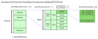
Where can I see the format of adcdata.txt?

Best regards,

  • I was able to get the adcdata.txt from this procedure.
    I saw that this file contains (no of adc samples) x (no of chirps per burst) x (no of bursts per frame) x (no of frames) x (no of rx antennas) lines of signed integer values.
    Can I understand that these values are MOSI and the format is in this order as well?

    I saw that the adcdata.txt contained 16bit width value with 16bit AD settings.
    But I have tried monitoring the SPI (MOSI) port with an oscilloscope and only see low level data, is this as expected?
    Are you adjusting the gain in the script?

  • Hi 

    PFA the document with steps to modify the demo and capture the SPI data and process it

    Steps for Raw ADC Data Streaming in IWRL6432.pdf

    The section "Post Processing of Captured Data" provides details about the format and steps process the data

    Regards

  • There is no gain adjustment done in the script. Data received is plotted

    Let me know if you are able to make progress with the pdf provided above

    Regards

  • Thank you for your support.
    I adjusted the script a little and was able to get the following data. I think I got the expected results.
    Results with(R) and without(L) an obstacle in front of the antenna.


    I want to check just to be sure.
    I couldn't check the image since it was too rough, but is the following correct?

    > 3. Disable the default configuration sent out via mmw_cli.c
    char* radarCmdString[MAX_RADAR_CMD] =
    {
    #if 0
    ...
    #endif
    };

    > 4. Update the linker.cmd file as described below.
    SECTIONS
    {
    /* This has the M4F entry point and vector table, this MUST be at 0x0 */
    .vectors:{} palign(8) > M4F_VECS
    .bss: {} palign(8) > M4F_RAM12 | M4F_RAM3 /* This is where uninitialized globals go */
    RUN_START(__BSS_START)
    RUN_END(__BSS_END)
    .text: {} align(8) >> M4F_RAM12 | M4F_RAM3 /* This is where code resides */
    .data: {} align(8) >> M4F_RAM12 | M4F_RAM3 /* This is where initialized globals and static go */
    .rodata: {} align(8) >> M4F_RAM12 | M4F_RAM3 /* This is where const's go */
    .sysmem: {} palign(8) > M4F_RBL /* This is where the malloc heap goes */
    .stack: {} palign(8) > M4F_RBL /* This is where the main() stack goes */
    .l3: {} palign(8) > HWASS_SHM_MEM /* This is where L3 data goes */
    }

    Best regards,

  • Hi

    Your steps are correct. But it is difficult to comment about the correctness of the plots without knowing the test scenario.

    Can you place a corner reflector at a designated distance and check if you see a distinct plot in the 1D FFT.

    Also, does the peak in 1D fft move as you change the position of the corner reflector

    Regards

  • Yes, I have confirmed this. Thank you.

    I have one more question.
    If I set ChirpRfFreqSlope to 0, will it work properly?
    I want to output a fixed frequency chirp signal for debugging purposes, but when I tried it, the ADC data level became very low. Is this noise?

    Best regards,

  • Hi,

    could you please provide a new Version of the .pdf file? The pictures of the .pdf are blurred. I am also trying to stream ADC with SPI but with IWRL6432AOP Device. Which demo and which .cfg is recommended for AOP device in this case? Best Regards

  • Hi

    Reposting the pdf with clear images

    Raw ADC Data Streaming in IWRL6432.pdf

    You can start with motion and presence detect demo in the SDK and use the presence detect cfg

    Regard

  • If you want to use fixed frequency, you will have to use CW mode. You will not be able to get the data through this demo. You need CW mode setup for it

    Regards

  • Thank you for the replay, please continue telling me.

    dev.ti.com/.../MMWAVE_DEMO.html
    > The demo currently supports only a 2 TX BPM-MIMO scheme. In addition, it supports only uniform chirp distribution within the frame (“Normal Mode”), namely single burst per frame, and even number of chirps per burst.

    Is this information correct? Or have I missed something?
    I could not change NumOfChirpsInBurst to something other than 2 for the mmWave demo.
    (I could also set the burst count to more than 1.)

    I understand the format of the ADC data is as follows:


    How should I understand the case of 2Tx BPM-MIMO?
    I also saw the ADC_parser(SDK tools) plots showing Txn->Rxm.

  • Hi,

    Is there any reason you want to use MMWAVE DEMO. You can use motion and presence detect demo. Motion and presence detect demo supports both TDM and BPM-MIMO mode. MMWAVE DEMO is designed for slightly different application. For streaming out ADC data over SPI, our recommendation is to use motion and presence detect demo which supports both the modes. 

    While using the 2Tx BPM-MIMO mode, you will have to demodulate the data (Tx1+Tx2 and Tx1-Tx2) across chirps

    Regards

  • I thought I needed to use the mmW demo to capture ADC data from SPI, but I understood that Raw ADC Data Streaming in IWRL6432.pdf you attached was for the motion and presence detection demo.
    I was able to make appimage using the motion and presence detection demo, thank you.

    Best regards,

  • Good to know that you were able to work with motion and presence detect demo

    Regards

  • Hi, 

    I have a question about the amplitude level of the ADC data.

    I saw that when I change ChirpRfFreqSlope from a small value (>0) to a large value, the ADC amplitude level also tends to change from small to large accordingly.
    Is this as expected?

    I set all parameters except ChirpRfFreqSlope to the same setting.
    I observed this without any reflective objects.

    Best regards

  • Hi,

    ChirpRfFreqSlope does not have any impact on the ADC amplitude. Only Rx gain determines the amplitude of the ADC samples.

    You can check with a reflective objects

    Regards

  • HI, 

    I tried to obtain ADC data by changing only ChirpRfFreqSlope while covering the board with a pan, and I saw that the ADC amplitude level changed according to the change in ChirpRfFreqSlope.
    I have not set the RxGain specifically, but I understand that it does not change with changes to ChirpRfFreqSlope.

    The firmware I am using is the Motion and presence detect demo example with ADC output via SPI enabled, and no changes have been made to the main processing.
    I am attaching the commands I used for the measurements and the results.

    ChirpRfFreqSlope_test_20240723_00.pptx
    Could you please check that there are no mistakes in the commands?

    Best regards

  • Hi,

    As the board is covered with a metal object, the setup may not be correct. Also, the ADC amplitude swing seems on the higher side, this could be because of the strong reflector closeby which could be leading to saturation.

    ADC amplitude is influenced by the Coupling between Tx and Rx. So, the chirp slope plays a role in influencing the coupling

    Please refer to the section 3 Risk of Receiver ADC Saturation in the below document, which indicates that slope affects the adc amplitude (Sorry for the miscommunication in the earlier reply)

    https://www.ti.com/lit/an/swra820/swra820.pdf?ts=1721985173817&ref_url=https%253A%252F%252Fwww.google.com%252F

    Is it possible to test with a strong reflector at distance of 1-2m? Then it could convey the correct picture

    Regards

  • Hi, Thank you for your support.

    I adjusted the gain and found it worked fine in our testing.

    Best regads,

  • Good to know that it worked for you

    Regards