This thread has been locked.

If you have a related question, please click the "Ask a related question" button in the top right corner. The newly created question will be automatically linked to this question.

TMAG5253: Need help choosing the magnet

Part Number: TMAG5253

Tool/software:

Dear Texas Instruments Team,

I am using the TMAG5253 in a game controller for the trigger functionality. The TMAG5253EVM helped me design the mechanism, but I have a few questions.

First, let me explain my setup. Below is an image showing the configuration similar to TMAG5253EVM but as you can see, there is a strong neodymium magnet beside the sensor, causing a constant magnetic flux density of 3-10 mT (measured using TIMSS).

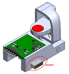
When I use the same configuration as the TMAG5253EVM, which has a TMAG5253A1DMR sensor with a magnetic sensitivity of ±20 mT, I am losing the detection range. Therefore, I assume I need to choose either the A2: ±40 mT or the A3: ±80 mT sensor variant. Also, I believe the TMAG5253EVM uses a ferrite magnet considering the low sensitivity of the sensor used. However, I think I can't do the same because I need to overcome 10 mT and choose a magnet that can produce a maximum magnetic flux density around ±40 mT or ±80 mT, depending on the sensor.

My questions are:

  1. Is my method correct for deciding which magnet to use?
  2. How do I choose between the ±40 mT or ±80 mT sensor variants? Does it solely depend on the magnet I use?
  3. Should I opt for the ±80 mT sensor variant considering the presence of a nearby magnet and to account for a safety margin?

Thank you for your valuable assistance.

  • Sharu,

    Thanks for reaching out on E2E.  Your approach seems to be good.  Magnetic fields are typically additive up to the point where magnetic fields start to become de-polarized.  Neodymium magnets are able to damage ceramic ferrite types.

    One concern to make sure you consider is the interaction between the two magnets.  Depending on the polarization you might attract or repel the trigger magnet.  I suppose this may be your intent to remove the need for a spring.

    Having a fixed position magnet next to the sensor will create an offset, and as a result you might saturate on the high side and leave unused margin on the low side.  Since your offset can be as much as 50% the maximum input range, you will likely want to use the larger range.  What is appropriate will depend entirely on the magnet you choose to the replace the ceramic one in the EVM.  I would typically recommend trying to get your inputs varying between 10%-90% of the full scale input range to allow for mechanical tolerances. If you think you'll see an input much higher than this when using the +/-40mT range, then I would recommend the +/-80mT option to avoid saturating the input.

    Thanks,

    Scott

  • Scott,
    Thank you so much for your insight that makes complete sense. From what i understand i think ill go ahead with  ±80mT because from my tests i did on TIMSS using the magnet properties that i can source locally i get a max input around 40-100mT.

    After more tests on the initial prototypes ill settle on a  lower range sensor if i don't see the need for higher range sensor.

    Thanks,
    Sharu

  • Sharu,

    Glad I could help.  Hope the design continues with success.

    Thanks,

    Scott