


Tool/software:
Hello team,
Please review the schematic of LMP91000 and provide the feedback and also what is the use of C1 and C2 what needs to be connected in schematic.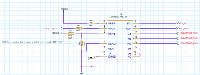
Tool/software:
Hello team,
Please review the schematic of LMP91000 and provide the feedback and also what is the use of C1 and C2 what needs to be connected in schematic.
