AWR1642BOOST: Range Resolution vs Spectral Resolution and SNR for Estimation of Range from Concrete Wall

Part Number: AWR1642BOOST
Other Parts Discussed in Thread: AWR1642, AWR2944

Tool/software:

Greetings Forum!
I hope this blog finds everyone in the best of health and spirits.

I am working on an application where I have to estimate the range from a vertical concrete wall at a grazing angle of 90 degrees from the radar's frame of reference.

We initially proceeded with a very high range resolution of 3.75cm but given the very wide HPBW of antenna in the azimuth plane, we observed multiple targets in the range profile since the radar considers the 2D patches of antenna illumination as separate targets due to very high range resolution. 

Due to this separation of targets, we were getting a very low SNR and per the radar range equation, we were able to estimate the Normalized RCS of the wall as 0.02, an unrealistically low approximation given high reflection ability of concrete for a 77GHz source. We concluded that the RCS of the wall can be increased if individual scatterers can be combined into a single range bin by making the range resolution coarse at 1m. 

Subsequently, we were able to observe the wall as a single target on the range profile however, the SNR has decreased instead of increasing. 

We are unable to fathom this counterintuitive behavior. Your guidance in this matter is highly solicited.

Moreover, there is a slight confusion in my understanding of how range resolution and spectral resolution are interrelated. Per my understanding, the range resolution is a physical phenomenon governed by c/2B being the minimum distance below which two objects cannot be discerned as separate objects. If I consider each target in radar FOV as being capable to generating a unique beat frequency, it is the spectral resolution that must be fine enough such that each target appears as a separate peak in the range profile after range-FFT. I want to know how the range resolution.

Please correct me if am wrong, the FFT size must be large enough to ensure that the physical limitation of range resolution can be achieved by applying the FFT of appropriate size on the time domain signal. 

My waveform specifications ensue below, 

Max Range:256m

FFT Size: 256

S=2.92 MHz/μs

T=51.37 μs

B=150 MHz

Fs=5209 KSPS

IFmax=5MHz (governed by Fs, complex baseband architecture)

ΔR=1m

Δf= 20.3KHz

Your guidance for both issues is highly awaited.

Best Regards

Maaz Ali Awan

  • Hi Maaz,

    AWR1642 is not designed for long range detections. If your requirement is to detect around 200m, we suggest you to use AWR2944 instead of AWR1642. AWR1642 is for short range detections.

    Short Range Radar Reference Design Using AWR1642 (Rev. B) (ti.com)

    Regards,

    Samhitha

  • Greetings Dear Samhitha!

    Thank you for the response and apologies for the delayed response.

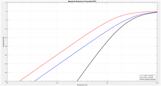
    Actually, my work on the mmWave radars has an academic research scope. I am completely aware of the mmWave product line and their offerings. The highlighted issue was a limitation in my understanding. However, I have been able to identify that it is indeed the High Pass Filter that is causing the return to be severely attenuated. I tried increasing the range by slowing down the chirp slope but ended up with an Intermediate Frequency value for my target that falls in the band-stop range of the High Pass Filter.

    This now brings up the question that if there is a possibility to bypass the High Pass Filter digitally. I totally understand that the rationale for having such a filter is to suppress the coupling signature from Tx antenna. To the best of my understanding, there is a function in the out of box demo that removes the coupling signature using Digital Signal Processing. I want to characterize the performance of digitally suppressing the coupling signature while bypassing the High Pass Filter altogether.

    Looking forward to a favorable response.

    Best Regards

    Maaz Ali Awan

  • Hello,

    There is no option to bypass the HPF. You can reduce the HPF cutoff frequencies to the lowest programmable value but they cannot be disabled.

    Regards,

    Adrian

  • Thank you Adrian!
    Is my understanding regarding the purpose of HPF to suppress the coupling signal correct?

    Furthermore, I would like to request that since the following frequency response of the HPF filter is just an estimate, can I get the Look Up Table for the HPF so that I can estimate the effect of HPF at an IF value of say 39KHz? I shall be really grateful for my post-processing analysis to compare the impact of HPF between 02 distinct IF values. I can then replicate the filter in Matlab and add an inverse of this HPF as a gain block to simulate how my signal would have looked without the HPF.

    If for example, the coupling signal becomes a problem, i can use the coupling signature removal algorithm from the out of box demo to suppress it.

    Please advise


    Best Regards

    Maaz 

  • Hello,

    Do you have a field sales representative you can reach out to? We have some matlab simulation but this needs to be provided through NDA so you need to go through the field sales office.

    Below are attenuation values at a few key frequencies which you could use to extrapolate a best fit line for rough estimation.

    Freq
    175k 350k 500k 750k 900k
    2.00E+04 30 36 38 >40 >40
    1.00E+05 18 22 28 28 33
    1.00E+06 13 13 13 14 14

    Regards,

    Adrian

  • Greetings!
    Thank you so much for the response. 

    I think the provided table more than gets the job done for our use case.

    Best Regards

    Maaz Ali