- Ask a related questionWhat is a related question?A related question is a question created from another question. When the related question is created, it will be automatically linked to the original question.
This thread has been locked.
If you have a related question, please click the "Ask a related question" button in the top right corner. The newly created question will be automatically linked to this question.
Tool/software:
Hi,
I've been evaluating the AWR6843AOPEVM together with a DCA1000EVM using mmWave Studio. For this, I put a radar reflector at several known distances (1-3m). As config, I use the default values.
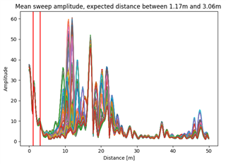
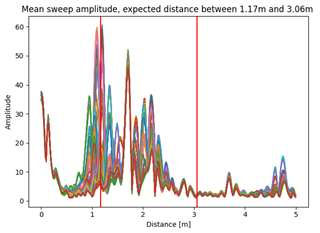
However, the range amplitude plot did not show peaks where I expected them at all. After some trial and error, it occurred to me that the range resolution calculated in the post-processing divided by 10 would give more reasonable, but still not sufficient, results. See images below where the reflector is moving between appr. 1.17m and 3.06m. The first diagram uses the range resolution calculated by mmWave Studio (19,53cm), for the second this value was divided by 10 (so 1,95cm).
Is there an explanation for this?
Thanks in advance!
HI, there:
If the calculated range resolution is 19.53cm. and your target range is 1.17m ~ 3.06m. Is it possible you first figure, the range unit is wrong. Instead of in the unit of meter, maybe it is in unit of range bin index?
In addition, the range FFT output is not clean at all, can you move to a cleaner environment and check again? I would expect a relative clean target. If it is not improved, I would doubt whether your data capture and parsing are correct.
Best,
Zigang
Both figures were produced by the same algorithm, the only difference is the range per bin (19cm vs 1,9cm).
The FFT output is plotted for all frames in one plot. As the reflector moves, the maximum is at different places within the given range.
Here is a plot of the FFT for the empty scene -recorded on a different day- without the reflector (using the default 19cm):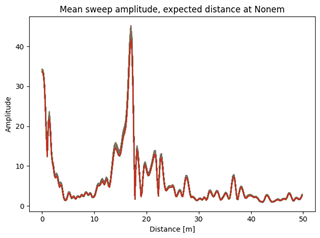
I do not have the possibility to move to a less cluttered area for the measurements.
Here are additional plots with the reflector at a static position (using the default 19cm):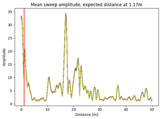
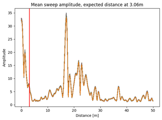
In the first plot, a change in amplitude is clearly visible at 10-12m while there is not much change in the distance below 10m. The second plot shows a not so clear amplitude change at 25m.
The capturing was done using mmWave Studio following the tutorial. To plot the data, I used readDCA100.m from the mmWave Studio folder to convert the data to a ".mat" format.
Hi, there:
In mmwave studio, we have postProc button. Have you checked the results from the mmwave studio build-in post processing? And is it similar to what you shown here?
Best,
Zigang
I've used the PostProc button, here are a few screenshots of the saved figures (in the order empty room, reflector at ~1m, reflector at ~3m, reflector moving between ~1-3m with ~1.26m/s):
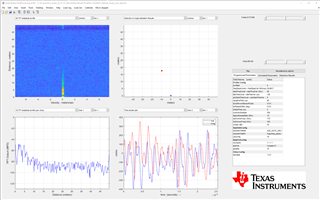
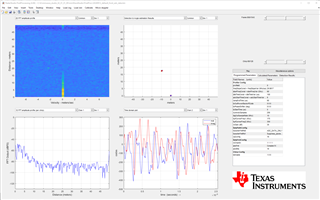
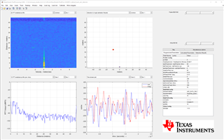
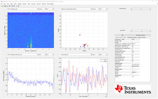
Additionally, I found the readDCA1000_6843.m script and converted the data with it. The results look better, but are still stretched compared to the expected results, see 4th figure, where the movement is detected between ~2m and ~5.50/6m instead of ~1m and ~3m.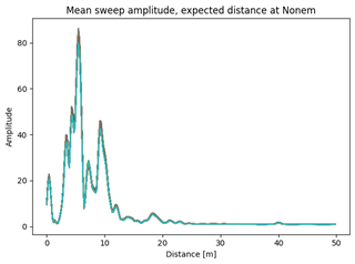
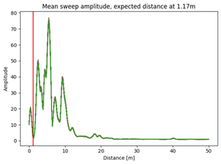
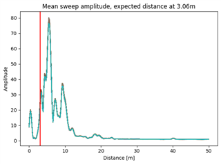
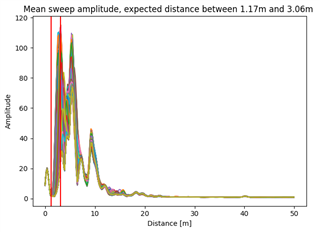
Here is how I read my data (in Python) to plot the range-amplitude figures:
for file in ["empty"]:
    num_antenna = 4
    num_chirps = 128
    num_samples = 256
    range_res = 0.1953
    data = mat73.loadmat(f"../20240912_TI/{file}/{file}.mat")['ans']
    num_frames = int(data.shape[1]/num_chirps/num_samples) # stopped by hand
    data2 = np.empty((num_antenna, num_frames, num_chirps, num_samples), dtype=np.complex128)

    fig, ax = plt.subplots()
    for frame in range(0, num_frames):
        y = None
        for antenna in range(0, num_antenna):
            if y is None:
                y = compute_distance(data[antenna][frame], num_chirps, num_samples)
            else:
                y += dist = compute_distance(data[antenna][frame], num_chirps, num_samples)

        y /= data.shape[0]
        ranges = []
        for r in range(0, y.shape[0]):
            ranges.append(r*range_res)
        ax.plot(ranges, y)
    ax.set_ylabel("Amplitude")
    ax.set_xlabel("Distance [m]")
    fig.tight_layout()
    plt.show()

def compute_distance(chirp_data, num_chirps, num_samples):
    range_fft = fft_spectrum(chirp_data, signal.blackmanharris(num_samples).reshape(1, num_samples))
    range_fft_abs = abs(range_fft)
    distance_data = np.divide(range_fft_abs.sum(axis=0), num_chirps)
    return distance_data
HI, there:
It is hard to imagine that the radar reflection from your target object is so small compare to all the other reflect signal between 4.5m~10m. And the same target reflection is weaker at 1m than 3m.
1) Can you try to enable the test source in mmwave studio frame configuration?
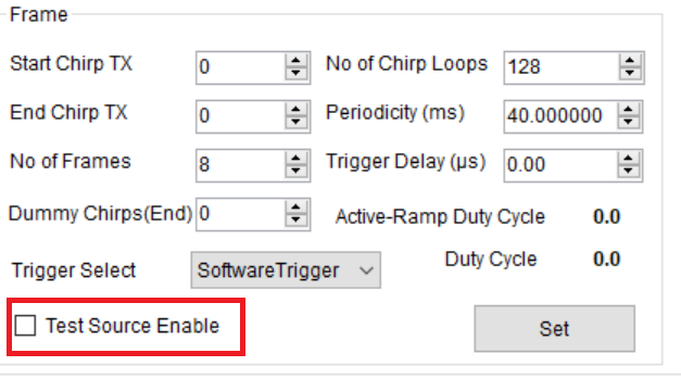
You should see a clean target at 5m with test source enable. If everything looks good, you can try:
2) Can you switch to a bigger corner reflector? And switch to a configuration file that has maximum range around 5m instead of 50m.
How did you parse the ADC data from the binary file.
Best,
Zigang
These are my settings for the TestSource (I didn't edit the given values):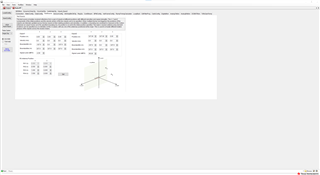
I would expect the peak to be at sqrt(3²+4²)=5m, as you stated.
In the PostProc figure I get the following values, which are not quite as expected: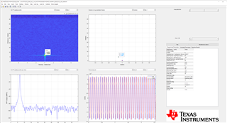
And my Python plots give the following results, which are again way off: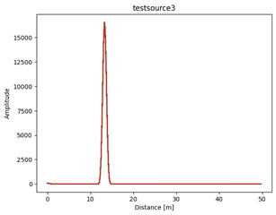
For the conversion of the binary adc data, I used the provided code from the TI application report "SWRA581B - Mmwave Radar Device ADC Raw Data Capture" (Rev. Oct 2018) from section 9.2.
%%% This script is used to read the binary file produced by the DCA1000
%%% and Mmwave Studio
%%% Command to run in Matlab GUI - readDCA1000('<ADC capture bin file>')
function [retVal] = readDCA1000_6843(fileName)
%% global variables
% change based on sensor config
numADCSamples = 256; % number of ADC samples per chirp
numADCBits = 16; % number of ADC bits per sample
numRX = 4; % number of receivers
numLanes = 2; % do not change. number of lanes is always 2
isReal = 0; % set to 1 if real only data, 0 if complex data0
%% read file
% read .bin file
fid = fopen(fileName,'r');
adcData = fread(fid, 'int16');
% if 12 or 14 bits ADC per sample compensate for sign extension
if numADCBits ~= 16
    l_max = 2^(numADCBits-1)-1;
    adcData(adcData > l_max) = adcData(adcData > l_max) - 2^numADCBits;
end
fclose(fid);
fileSize = size(adcData, 1);
% real data reshape, filesize = numADCSamples*numChirps
if isReal
    numChirps = fileSize/numADCSamples/numRX;
    LVDS = zeros(1, fileSize);
    %create column for each chirp
    LVDS = reshape(adcData, numADCSamples*numRX, numChirps);
    %each row is data from one chirp
    LVDS = LVDS.';
else
    % for complex data
    % filesize = 2 * numADCSamples*numChirps
    numChirps = fileSize/2/numADCSamples/numRX;
    LVDS = zeros(1, fileSize/2);
    %combine real and imaginary part into complex data
    %read in file: 2I is followed by 2Q
    counter = 1;
    for i=1:4:fileSize-1
        LVDS(1,counter) = adcData(i) + sqrt(-1)*adcData(i+2); LVDS(1,counter+1) = adcData(i+1)+sqrt(-1)*adcData(i+3); counter = counter + 2;
    end
    % create column for each chirp
    LVDS = reshape(LVDS, numADCSamples*numRX, numChirps);
    %each row is data from one chirp
    LVDS = LVDS.';
end
%organize data per RX
adcData = zeros(numRX,numChirps*numADCSamples);
for row = 1:numRX
    for i = 1: numChirps
        adcData(row, (i-1)*numADCSamples+1:i*numADCSamples) = LVDS(i, (row-1)*numADCSamples+1:row*numADCSamples);
    end
end
% return receiver data
retVal = adcData;HI, there:
Can you send all the sensor configuration information?
Best,
Zigang
Sure, here are all the tabs in mmWave Studio (sensor not connected), which I use: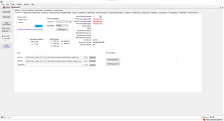
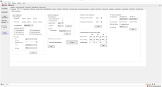
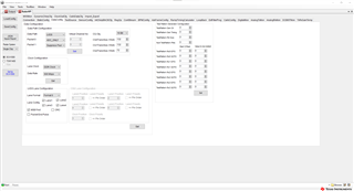
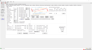
Of course, for the test in the previous reply Test Source is checked in the last picture.
Hi, there:
You have set LVDS lane wrong. In addition, I would recommend you to try TDM only first. Only enable one TX for each chirp.
Check the step by step instructions for mmwave studio programming
https://dev.ti.com/tirex/explore/node?node=A__AGTrhNYW8jE6cMxbovlfaA__radar_toolbox__1AslXXD__LATEST
The following figure shows only two LVDS should be enabled. There is only two LVDS lanes inside xWR6843 device.
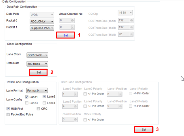
Best,
Zigang
I've checked again, this time with the sensor connected, and noticed that then only LVDS Lane 1 and 2 are checked. Sorry for the confusion. I've followed the guide from your answer. I am unsure, however, at which point in the order I set the test source. Might this have an influence? Currently, I go through the tabs from left to right.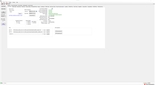
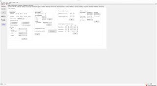
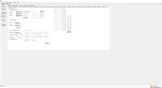
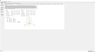
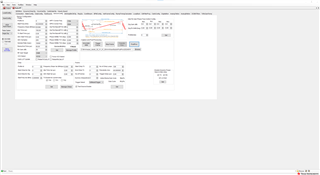
Where do I change to TDM? I haven't found the option.
Hi, there:
You are only enable one TX in your chirp design, so you are already using TDM.
What is postProc show? Is the target located at 5m now?
Best,
Zigang
It is still the same as 4 days ago, since I didn't have to change anything then.
I also get the same result, when I only choose one Tx antenna in the StaticConfig tab instead of all three.
Hi, there:
I tried on my side, and see the same thing. The peak was over 6 meters when the test vector was supposed to be 5m. Maybe there is something wrong with the test vector generation.
I would suggest you to go back to your real target and try with the following profile configure (which gives the max range of 5.33m). Let me know whether your target location makes more sense.
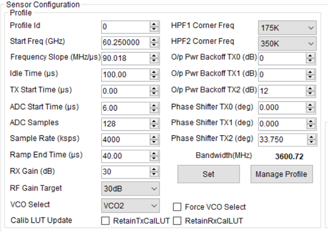
Best,
Zigang
Thank you for looking into it.
I've tried the new configuration. The results are still not satisfying, as the detected movements are in a range above ~4m.
First of all, I've noticed that the max range is 6.609m, not 5.33m.
This is how the moving target looks in PostProc: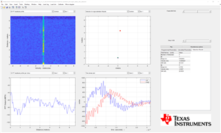
and in my range plot: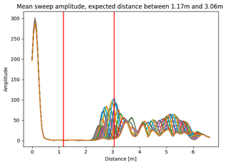
No reflector for comparison: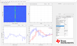
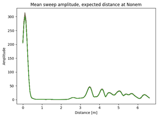
HI, there:
You will have to try with a static target with higher RCS. Use a corner reflector and keep it static.
Best,
Zignag
I am using a multi-corner reflector with a RCS that is already bigger than the targets I intend to detect.
How would a reflector with a bigger RCS help with correcting the distance?
Not only that, but I've tested the same setup with radar sensors from different vendors, and the detection of the others work perfectly fine.
Could it be that we're talking about different issues (detection at the wrong distance vs. the amplitude of the detection)?
As this discussion is going on for quite some time without results, would it be possible to schedule a call or video conference to sort it out?
Hi, Daphne:
The peak in your picture is not very obvious, that is the reason I recommend for a bigger target.
At this point, I would recommend you to try OOB demo, and OOB visualizer to see whether you would see more reasonable result. So that we know if it is a hardware issue.
Best,
Zigang
I have tested the OOB demo with a static reflector and the distance results look better so far, even for different configs. Left figure is for 1m, right figure for 3m.
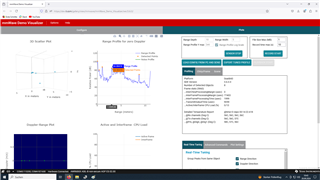
But I've noticed that the part of or the whole range spectrum glitches every few seconds. I tried Firefox and Chrome and also different config settings, but the behaviour was the same. The downloadable visualizer didn't work for me, as it got stuck when searching for COM ports.
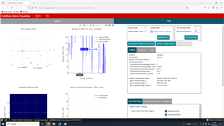
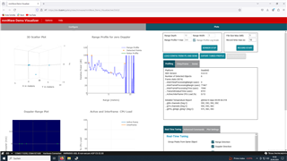
Might that be a hint for a fault or connection issues?
Do you have any recommendation on how to continue? In my use case I have to record the raw data for further processing and thus need to utilize the DCA1000EVM and mmWave Studio as far as I understood. I am out of office for the next two weeks, so I will not be able to answer or test anything during that time.
Hi, there:
I would recommend you to try some another device.
Best,
Zigang