This thread has been locked.

If you have a related question, please click the "Ask a related question" button in the top right corner. The newly created question will be automatically linked to this question.

LDC1614: Measurement Drift over time

Part Number: LDC1614

Tool/software:

Hello, it is me again.

Since this forum was so helpful the last time, I thought I'd try again!

First off, I've seen and read the following threads already:

On to our problem:

The measurement, as was described here (https://e2e.ti.com/support/sensors-group/sensors/f/sensors-forum/1443373/ldc1614-wrap-around-noise) works pretty well indeed. We have one remaining problem: a drift over time. At first we used a pretty cheap LDO that was not temperature stable (3.21V to 3.29V from 0°C to 100°C). We replaced them with the TI TLV1117LV33DCYR which seem really stable (only 0.5mV deviation from 25°C to 100°C). However, the problem only marginally improved. As seen in the following plots, the counts first drop and then increase again (measurement time: 5:40h, no changes in the setup during that time, room temperature was stable as well):

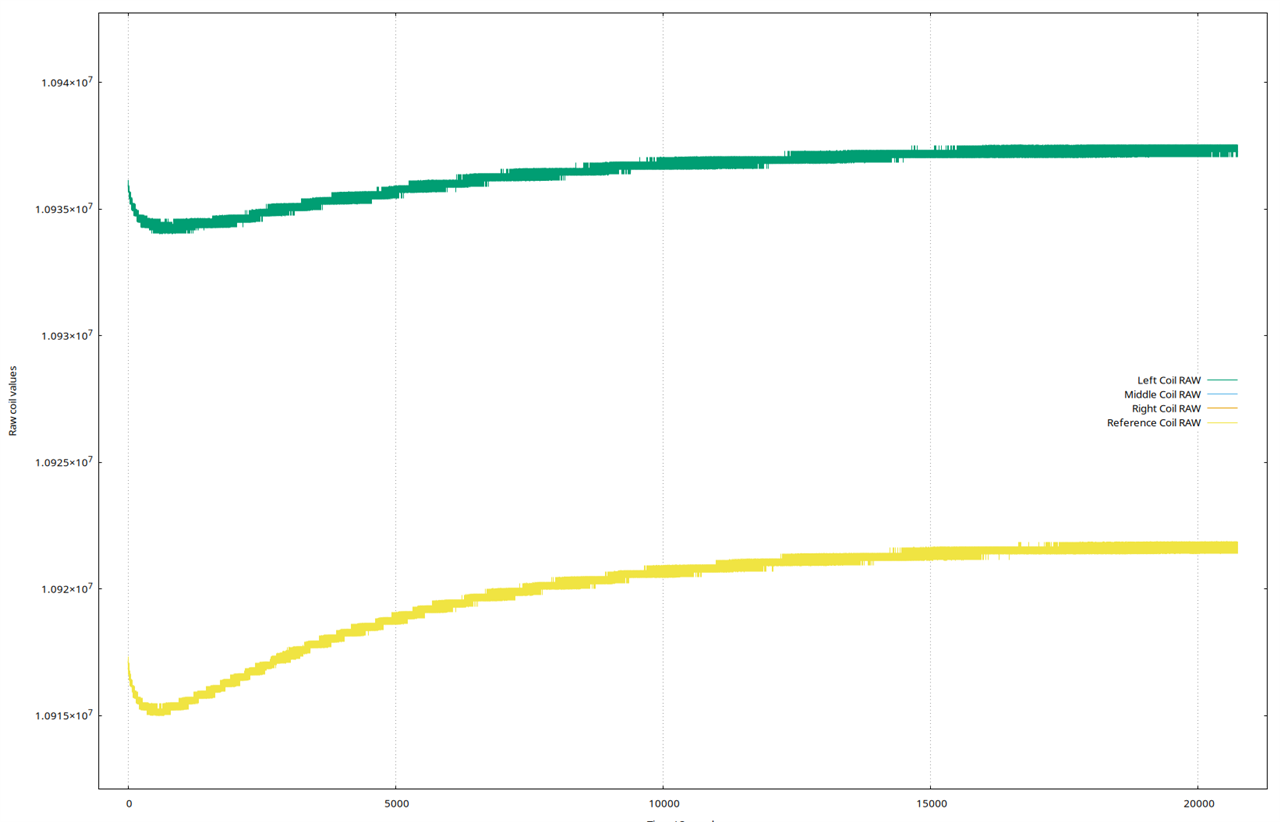
Here's also a zoomed and normalized view:

We do use NP0 capacitors for our four coils. Baseline compensation is hard since left, middle and right are engaged at all times and the measured metal rod changes. The ref coil is independent of these changes, but its drift is also a bit different. Moreover, the clock is temperature compensated as well.

We're now at a point where we don't see any way of improving our results besides improving the SNR (which we will do, later). Is this drift expected? We assumed the setup would be more stable than what we observer right now. Is the drift something that happens in the LDC? Because I'm pretty sure we can be sure that both the LDO and the clock are stable.

Thank you for any comments!

  • Tim,

    Just to confirm: were there temp changes behind your plots, or do they represent room temp drift over time?

    Some drift over temp and time will be inevitable. 
    What are the acceptable limits for your application?

    Regards,
    John

  • The rom temperature was more or less constant, the only source for a change of temperature is the MCU, the LDC and the LDO. However, I can't imagine that the temperature needed more than 5 hours to reach a steady state.

    In the current setup I'd say a drift of 1/4 what we see here would be ok, but in general it is hard to define. My main question is if this drift here is what is expected, or if there is something more or less obvious that we're doing wrong

  • Tim,

    To be honest, we don't have a lot of readily available data on the stability of these device's outputs.
    One piece of info that might be relevant is that these devices are good at detecting changes in inductance, but not absolute inductance. 
    The drift you are seeing is probably hints at the origins of this idea.

    The other consideration is that output data results from the interaction of two oscillators. 
    The first oscillator is the reference clock, and the other is the LDC  sensor (aka the inductive sensor & resonant cap) in conjunction with the internal LC-driver circuitry forming a negative gm oscillator. Any drift in these two oscillators is summed and results in the total drift on the output data. 

    I added some approximate gridlines to the images your provided and tried to make some "guess-timates" of the output data stability based on the images:
    Left Coil: ∼270ppm
    Ref Coil:  ~1800ppm

    Not sure if it tells us anything useful...... I will look to see if we have any internal data that we can use for comparison.

    As I'm writing this, it occurs that the data's output stability will be dependent on the sum total of the two oscillators' drift over time, which can be destructive or constructive. I other words, if drift tends to consistently err in one direction, drift will be constructive and get worse over longer time intervals. If drift is more random from cycle-to-cycle then it may tend to cancel (destructive), especially over longer time intervals (e.g. more averaging).
    And the time intervals will interact with the ref clock frequency and the sensor frequency.

    With that in mind, some questions:

    1. Have you evaluated output stability for different values of RCOUNT and the sensor frequency?
    2. If so, does stability change?
    3. What values of L and C are you using for the sensors, and are there approximate values for Q and/or Rp?

    regards,
    John