This thread has been locked.

If you have a related question, please click the "Ask a related question" button in the top right corner. The newly created question will be automatically linked to this question.

FDC1004 behaviour with basic test

Other Parts Discussed in Thread: FDC1004, FDC1004EVM

Hi,

Am doing basic capacitance test with FDC1004.

39pF input am giving to FDC1004. The output scenario follows,

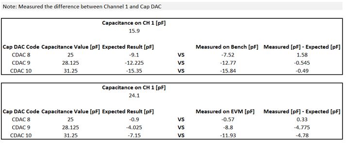
1) Coffset = 25.0 and read capacitance from capacitive measurement registers is 13.968pF. The output is 13.968+25.0=38.968pF which is almost matching with 39pF.

2) Coffset = 28.125 and read capacitance from capacitive measurement registers is 4.830pF. The output is 4.830+28.125=32.955pF which is not near to 39pF.

From the above two scenarios, first one is correct. But second one is wrong. Why it's misbehaving when i change the offset from 25.0 to 28.125 eventhough input capacitance is within measurable range.

  • Hi:

    Can you describe the setup you are using and how you are testing it? Are you using the FDC1004EVM? Are you using the GUI? Or are you using your own prototype board. Where is the 39pF input coming from, a fixed capacitor or an actual sensor, etc...? Typically, deviations in measurements are from the setup being inconsistent.

    Thanks

    -David Wang

    Capacitive Sensing Applications

  • Hi David,

    1) We designed our own board and with our own firmware we testing it.

    2) FDC1004EVM we are not using it.

    3) GUI also we are not using.

    4) Fixed 39pF near to CIN1 and other end of capacitor goes to GND

    Also PFA file of our our outpur as i explained previously.CAP_Measurement.TXT

  • Do you have a layout of the FDC section? You mentioned that you have a fixed 39pF cap near CIN1, can you show me where it is. Do you have a sensor connected to CIN1 while measuring the cap? Any SHLDs being used?

    Thanks
    -David Wang
    Capacitive Sensing Applications
  • Hi David,

    I will share with you the layout and i need to get the permission from my management and some process needs to be followed. Mean while i have doubt on my code which is shown below.

    /*******Global Variables**************/

    union
    {
    unsigned char Cap1_byte[4];
    unsigned long Cap1_Count;
    }CAP1;
    unsigned char CAPDAC_Reg_char[2], debug_buf[200];
    unsigned char CAPDAC_Range, Cap_Read_Procedure;
    unsigned char Stable_Cnt;
    unsigned int CAPDAC_Reg_int;
    float CAPDAC_offset;
    float Data_Reg_pF, Cap_fF;

    /*******Global Variables**************/


    void FDC_Read_Capacitance(void)
    {
           unsigned char buff[2];

           switch(Cap_Read_Procedure)
           {
                    case WRITE_CAPDAC_REGISTER:
                    if(I2CW_R(FDC1004_ADDRS, 0X08, (unsigned char*)&CAPDAC_Reg_char, 2, 0)==0)
                    {
                             I2C_STOP;
                             SEND_STRING_USART("\r\nCase1_FAIL");
                             Cap_Read_Procedure = WRITE_CAPDAC_REGISTER;
                    }
                    else
                    {
                             //SEND_STRING_USART("\r\nCase1_PASS");
                             Cap_Read_Procedure = WAIT_FOR_DATA_READY;
                    }
                    break;

                    case WAIT_FOR_DATA_READY:
                    if(I2CW_R(FDC1004_ADDRS, 0X0C, &buff[0], 2, 1) == 0)
                    {
                              I2C_STOP;
                              Cap_Read_Procedure = WRITE_CAPDAC_REGISTER;
                    }

                    if((buff[1]) & (0X08))
                    {
                              Cap_Read_Procedure = READ_CAPACITANCE;
                    }
                    else
                    {
                              Cap_Read_Procedure = WAIT_FOR_DATA_READY;
                    }
                    break;

                    case READ_CAPACITANCE:
                    //SEND_STRING_USART("\n\r Read Capacitance");
                    if(I2CW_R(FDC1004_ADDRS, 0X00, &buff[0], 2, 1) == 0)
                    {
                              I2C_STOP;
                              Cap_Read_Procedure = WRITE_CAPDAC_REGISTER;
                    }
                    CAP1.Cap1_byte[2] = buff[0];
                    CAP1.Cap1_byte[1] = buff[1];

                    _delay_ms(1);

                   if(I2CW_R(FDC1004_ADDRS, 0X01, &buff[0], 2, 1) == 0)
                   {
                              I2C_STOP;
                              Cap_Read_Procedure = WRITE_CAPDAC_REGISTER;
                   }

                   CAP1.Cap1_byte[0] = buff[0];
                   CAP1.Cap1_byte[3] = 0x00;

                   Data_Reg_pF = (CAP1.Cap1_Count/524288.0);

                   Cap_fF = ((Data_Reg_pF + CAPDAC_offset) * 1000);
                   sprintf((char*)&debug_buf, "Read_pF = %f Cap_fF = %f\tCAPDAC=%d\toffset=%f\n\r", Data_Reg_pF, Cap_fF, CAPDAC_Range, CAPDAC_offset);
                   SEND_STRING_USART((char*)debug_buf);
                   Cap_Read_Procedure = FIND_CAPDAC;
                   break;

                   case FIND_CAPDAC:
                   //SEND_STRING_USART("\n\r Find CAPDAC");
                   if(CAPDAC_Range == 8)
                   {
                              Stable_Cnt++;
                              if(Stable_Cnt>9)
                              {
                                         Stable_Cnt = 0;
                                         CAPDAC_Range = 9;
                              }
                   }
                   else
                   {
                              Stable_Cnt++;
                              if(Stable_Cnt>9)
                              {
                                        Stable_Cnt = 0;
                                        CAPDAC_Range = 8;
                              }
                   }
                  /*CAPDAC_Range++;
                  if(CAPDAC_Range>=32)
                  {
                             CAPDAC_Range = 0;
                  }*/
                  CAPDAC_offset = CAPDAC_Range*3.125;
                  CAPDAC_Reg_int = (0x1000 | (CAPDAC_Range<<5));
                  CAPDAC_Reg_char[0] = (unsigned char)((CAPDAC_Reg_int>>8) & 0x00FF);
                  CAPDAC_Reg_char[1] = (unsigned char)((CAPDAC_Reg_int) & 0x00FF);
                  Cap_Read_Procedure = WRITE_CAPDAC_REGISTER;
                  break;
           }
    }

    int main(void)
    {
              while(1)

             {
                     _delay_ms(100);
                     FDC_Read_Capacitance();

    }
    }

    For the above program i connected 33pF fixed capacitor on input side and changing the CAPDAC 8 and 9[offset 25.0 and 28.125] respectively. Reading capacitance ten times CAPDAC with 8[offset 25.0] and another ten times CAPDAC with 9[offset 28.125]. But when i keep CAPDAC 8[offset 25.0] it's almost matching and am getting near 33pF but when i keep CAPDAC 9[offset 28.125] then am getting output 59.8pF. Same output file attached here. Am having doubt that is there any mistake am making in software.8508.CAP_Measurement.TXT


  • The code above looks fine, but where exactly are you getting CAP1.Cap1_Count in Data_Reg_pF = (CAP1.Cap1_Count/524288.0)?

    One thing that you should try is to see other CAPDAC offsets besides 8 to 9, try maybe 6 through 10 to see if it's consistent. Have you also tried another FDC1004 or board to make sure that it's an isolated issue? There may be something with the layout that could be causing it, but I would have to see it to confirm my intuition.

    Thanks
    -David Wang
    Capacitive Sensing Applications
  • Hi David,

    union data type i used to convert 3 bytes in to 24 bit long value. For example 

    union
    {
    unsigned char Cap1_byte[4]; 
    unsigned long Cap1_Count; 
    }CAP1;

    CAP1.Cap1_byte[3] = 0x00; 
    CAP1.Cap1_byte[2] = 0x6D;

    CAP1.Cap1_byte[1] = 0x10; 
    CAP1.Cap1_byte[0] = 0x47;

    Then CAP1.Cap1_Count is 7147591.

    I was doing one mistake in my previous method testing. I was not considering 2's complement. For example if i get a count 0xFDF4FA which is equal to 16643322 and if i divide that count by 2^19 then we will get 31.7446. But actually capacitance can't be read more than 16pF. So it was wrong but the actual value for 0xFDF4FA would be -0.2664

    But still in my previous testing it won't match with actual capacitance. My i/p fixed capacitor is 33pF. The following are the results,

    1) CAPDAC = 8 and Offset = 25.0 then i/p read capacitance is 8.883 so my o/p is 25.0+8.883=33.883 which is almost matching.

    2) CAPDAC = 9 and Offset = 28.125 then i/p read capacitance is -0.2664 so my o/p is 28.125+(-0.2664)=27.8586 which is not at all matching.

    Also i did some more work around to understand the scenario and follows,

    I connected fixed 22pF on my i/p side and tried with possible CAPDACs and follows,

    1) CAPDAC = 3 and Offset = 9.375 then i/p read capacitance is 13.6329 so my o/p is 9.375+13.6329=23.0079 which is almost matching.

    2) CAPDAC = 4 and Offset = 12.5 then i/p read capacitance is 10.5739 so my o/p is 12.5+10.5739=23.0739 which is almost matching.

    3) CAPDAC = 5 and Offset = 15.625 then i/p read capacitance is 7.4721 so my o/p is 15.625+7.4721=23.0971 which is almost matching.

    4) CAPDAC = 6 and Offset = 18.75 then i/p read capacitance is 4.4895 so my o/p is 18.75+4.4895=23.2395 which is almost matching.

    5) CAPDAC = 7 and Offset = 21.875 then i/p read capacitance is 1.1588 so my o/p is 21.875+1.1588=23.0338 which is almost matching.

    6) CAPDAC = 8 and Offset = 25.0 then i/p read capacitance is -1.8387 so my o/p is 25.0+(-1.8387)=23.1613 which is almost matching.

    7) CAPDAC = 9 and Offset = 28.125 then i/p read capacitance is -10.9797 so my o/p is 28.125+(-10.9797)=17.1453 which is not at all matching.

    8) CAPDAC = 10 and Offset = 31.25 then i/p read capacitance is -14.0933 so my o/p is 31.25+(-14.0933)=17.1567 which is not at all matching.

    From the above test whenever CAPDAC changes from 8(offset 25.0) to 9(offset 28.125) or from 9(offset 28.125) to 10(offset 31.25) we are finding this misbehaviour. We tried with fixed 22pF, 33PF and 39pF in all cases the problem is happening when we change the CAPDAC as i said above.

    As i said sending layout is long process and still approval is pending from my management.


  • So there is an error in the datasheet that is being fixed. The output of the FDC1004 is a 2's complement number. You basically just need to divide it by 2^19 and then add whatever offset you have.

    If I can get the layout and or pictures of your setup, I might be able to visually see something that may be causing a problem.

    Let me also consult with the designers to see if they can pinpoint the issue.

    Thanks
    -David Wang
    Capacitive Sensing Applications
  • I checked with the Designers and Validation team, there has been no issue seen with this. A quick experiment was conducted.

    Using our bench board, the difference between measured and expected is never too high. Moore error on CAPDAC Code 8 is normal because we are activating the 4th bit "1000". Using the EVM board and software seems that passing between CAPDAC code 8 and code 9 the step is more than 1. It could be an error in the EVM GUI increasing the CAPDAC code.

    I would suggest trying another FDC part to verify that it's the part rather than the firmware or the hardware.

    Thanks

    -David Wang

    Capacitive Sensing Applications

  • Hi David,

    Thanks a lot for the experiments conducted.

    I did some workaround depends on my requirement. My application is Fuel level measurement and it's ranges from 25pF to 50pF. For that am directly choosing CAPDAC 12[offset is 37.5] which satisfies my complete range. With this i can able to achieve without error. I thought of automating the process of choosing CAPDAC irrespective of length of the pipes which varies 10pF to 90pF. Sensor X ranges from 10pF to 25pF, Sensor Y ranges from 25pF to 50pF and Sensor Z ranges from 45pF to 90pF. For every sensor hard coding the CAPDAC values depends on capacitance ranges. Could not automate the process of choosing CAPDAC since we had seen different behaviour in while changing the CAPDAC from 8 to 9 or from 9 to 10. But we had achieved the values by fixing the CAPDACs such a way that there will not be any much variation.

    Also from the above results i am having few doubts. In EVM there is a 4.7pF difference in CAPDAC 9 and 10 range. But in bench results i could see only 0.5pF difference in CAPDAC 9 and 10 range. But capacitance i/p is different in both the cases. Have you tried with 24.1pF in bench experiment with CAPDAC ranges 8, 9 and 10. Am having little doubt that may be same variation we can see in bench results too if i/p is 24.1pF.
  • From what we can see just by the numbers above, with using the EVM board and the GUI, it seems like it is passing between CAPDAC code 8 and code 9 the step is more than 1. It could be an error in the EVM GUI increasing the CAPDAC code.

    For instance:
    CAPDAC code 8 = Code 8
    CAPDAC code 9 = Code 10
    CAPDAC Code 10 = Code 11

    SO the missing code 9 will introduce error in all the next steps.

    This behavior is not seen in the bench results...

    Thanks
    -David Wang
    Capacitive Sensing Applications
  • Hello David,
    hello Kandhasamy,

    I would like to participate in your discussion, as I observe the same behavior as Kandhasamy.

    In my application, I have to measure capacities in the range from 0pF to 80pF.

    If I choose a CAPDAC less or equal to 8, the FDC1004 shows the expected behavior and the
    addition of the measurement value and CAPDAC leads to the correct result (with very small deviations).
    The problems occurs after increasing CAPDAC from 8 ( 25pF ) to 9 (28.125pF). After setting CAPDAC to 9,
    the addition of the measurement value and capdac, leads to a result which differs by approximately -6pF from the correct value.

    I observed this behavior first on my own hardware with my own firmware. I build up five prototypes but all show the same behavior.
    Later I used the TI Evaluation board to verify my setup.
    But the evaluation board shows the same behavior. To illustrate the problem, I have taken a measurement series with the evaluation board.
    I connected a fixed capacitance of 33pF to channel 1 and increased CAPDAC step by step.
    Therefore I used the TI software (FDC1004 EVM GUI 0.0.0.7).  The  graph shows the logged values.


    As the Evaluation Board shows exactly the same behavior as my own boards, I exclude a defect of the chip.
    I assume that it is due to the FDC setting. 

    To facilitate the error diagnosis I attached the log-file and the exported settings of the evaluation board.

    I would be very happy if you could find the reason or show me a kind of workaround.

    Another thing:
    This behavior repeats itself when switching from 27 to 28. Then another displacement in the curve can be seen.


    Kind Regards

    Michael

    Attachment:

    FDCLog.xls

    FDCSettings.xls

  • Hi David,

    Previously as you suggested i tried changing the FDC part. But it's not helping and found the same behaviour as i mentioned earlier.

    Hi Michael,

    As you rightly said, the behaviour remains same in any of the FDC board[EVM or own board]. But i can give you some sort of work around but am not sure how far it will work in your hardware.

    1) Use CAPDAC as 5[15.625pF] which will take care of almost 0 to 30pF.

    2) If capacitance goes above 30pF use CAPDAC 14[43.75pF] which will take care of 30pF to 58pF.

    3) If capacitance goes above 58pF then use CAPDAC 22[68.75pF] which will take care of 58pF to 80pF.

    Try with these 3 ranges of CAPDAC since your requirement is 0 to 80pF. I think this might help you to come out of that issue.

  • Hi Michael and Kandhasamy:

    Thanks for the input. Our team is looking into this more carefully since it seems not to be an isolated case. We will get back to you if we find anything useful or conclusion to this issue.

    Thanks
    -David Wang
    Capacitive Sensing Applications
  • Hello David,
    hello Kandhasamy,

    today I have been thinking about Kandhasamy`s proposal and I made some measurements to verify if this could work.

    I've made three measurements with different capacities (33pF, 57pF and 84pF).
    The problem I observed is, that every measurement with CAPDAC higher than 8 differs by approximately -6pF.
    Measurements with a capdac higher than 27 differ by approximately -12pF.

    At the moment I'm at a loss.
    I had suspected that the error is due to the configuration of the FDC registers.
    I therefore read the FDC registers after each measurement and compared the settings with the setting for CAPDAC < 9, but I could see no pattern.

    I saved all the measurement result in excel-file`s. One file for each measurement. Each file contains one sheet with the measurement values and the graph, and a sheet for each capdac setting.

    Here are the data:

    Measurement with 33pF connected at C1:

    Measurement_C1_33pF.xlsx

    Measurement with 57pF connected at C1:

    Measurement_C1_57pF.xlsx


    Measurement with 84pF connected at C1:

    Measurement_C1_84pF.xlsx


    I'll wait for the moment and take no further attempts.
    I'm looking forward to hearing from you, preferably with a solution. :-)

    If I can assist you with data or further information, please do not hesitate to ask.

    Kind Regards

    Michael

  • HI Michael and Kandhasamy:

    I talked to validation about this issue and they ran some experiments and looked at your data more careful. In final test, the CAPDAC is measured from code 0 to 7, trimmed for that, and then the rest of the codes are interpolated based on code 0 to 7. This introduces a gain error especially towards code 31. On bench, they measure all codes and trim so that's why this issue was never seen. Even at CAPDAC 8, there was a very small difference /error but not as significant as what you are seeing.

    The CAPDAC was not designed so that the full scale range is 0 to 100pF and be changed on the fly. It was only designed to offset the capacitance within the specified input capacitance range. One thing that you could do is to use the offset register to offset the measurements based on what they should be. The only drawback is that since there will be a variation from part to part, you cannot guarantee the modified measurement will be the same each time. It depends on your application and precision requirements.

    Hope that clears things up.

    Thanks
    -David Wang
    Capacitive Sensing Applications
  • Hello David,

    first of all I would like to thank you for your support and the quick response.

    I would like to hold on to the chip, even if the measured values differ in the upper regions. I've also been thinking about correcting the measurement values with a kind of correction table. However, it is not practicable determining a correction table for each part manually. At least not in series production.

    Here is what came up to my mind:

    In my application I have to measure two channels (C1 & C2).I could connect fixed capacitors to C3 and C4 which could serve as a kind of on board reference. The tolerance of these capacitors should be as small as possible. In this way I could determine the difference between the connected capacitance and the measured capacitance and create a kind of correction table for diffrent capdac values.

    With the values from the correction table I could correct the measured values of channel 1 and 2.

    This presupposes that the deviations is independent of the channel. For me this is difficult to verify. Maybe you or your colleagues have further information regarding the deviation between the channels.

    I'm not sure if this could work or whether it is a rather stupid idea.

    Maybe you can tell me your opinion.

    Best regards

    Michael

  • I'm not quite sure if that will work because there will be some deviations from part to part and among channels even though they try to trim the parts close to each other. I would assume that it would be dependent on your system requirements and accuracy/precision needed.

    You could try it and test it with other boards with different parts to determine if the variation becomes worse. That is something that we do not have data on.

    Thanks
    David Wang
    Capacitive Sensing Applications