This thread has been locked.

If you have a related question, please click the "Ask a related question" button in the top right corner. The newly created question will be automatically linked to this question.

TDC1000-GASEVM: TDC1000-GASEVM

Part Number: TDC1000-GASEVM

I'm currently conducting an experiment to see how the TOF varies with O2 Concentration.

I have a TDC1000-GASEVM/TDC1000-BSTEVM and am using the TDC1000_7200_EVM Software.

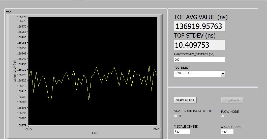
However, the graphical output of the measured TOF is very noisy and fluctuating by about 100ns, when it should be quite constant if the O2 concentration is constant (i'm using a portable oxygen concentrator to provide flow through the sensor) 

It also outputs a fluctuating TOF when the sensor isn't connected to any oxygen source.


  • Hi Madeleine,

    Could you please save and upload your config file and a capture of the TOF graph? How do the fluctuations compare between the oxygen source and open air? Are they about the same, or is one worse than the other?

    Regards,
  • Hi Scott,

    After completing more work on this today, i'm not so worried about the fluctuations, but more concerned about if my TOF is correct for my transducer measurements. 

    Please find attached my config file and screenshots of graphs at 90% and 20% O2. Additionally, my transducer is approximately 5.5cm, so using the formula TOF = distance between transducers/speed of sound I am not getting the correct values. 

    3162.TDC1000_Setup.txt
    Fullscreen
    1
    2
    3
    4
    5
    6
    7
    8
    9
    10
    11
    12
    13
    14
    15
    16
    17
    18
    19
    20
    21
    22
    23
    24
    25
    26
    27
    28
    29
    30
    31
    32
    33
    34
    35
    36
    37
    38
    39
    40
    41
    42
    43
    44
    45
    46
    47
    48
    49
    50
    51
    52
    TDC1000_Config0 04
    TDC1000_Config1 41
    TDC1000_Config2 20
    TDC1000_Config3 0D
    TDC1000_Config4 5F
    TDC1000_TOF-1 40
    TDC1000_TOF-0 1E
    TDC1000_Error_Flags 00
    TDC1000_Timeout 23
    TDC1000_Clock_Rate 01
    TDC1000_Conts_Trigger 00
    TDC7200_Config1 82
    TDC7200_Config2 40
    TDC7200_Interrupt_Status 06
    TDC7200_Interrupt_Mask 07
    TDC7200_Coarse_Cntr_Ov_H FF
    TDC7200_Coarse_Cntr_Ov_L FF
    TDC7200_Clock_Cntr_Ov_H FF
    TDC7200_Clock_Cntr_Ov_L FF
    TDC7200_Clock_Cntr_Stop_Mask_H 00
    TDC7200_Clock_Cntr_Stop_Mask_L 00
    TRIGGER_UPDATE_FREQ 0000
    TDC_AVG/STDEV_NUM_ELEMS 00C8
    SAVE_GRAPH_DATA_TO_FILE 00
    FLOW_MODE_SELECT 00
    Y-SCALE_CENTER 0032
    X-SCALE_RANGE 0032
    MEASURE_RTD1 00
    SAVE_RESULT_REGR_TO_FILE 00
    GRAPH_MULTI_STOPS 00
    TDC_SELECT 00
    TEMP_RTD_SELECT 00
    TEMP_RTD_MODE 00
    TEMP_AVG/STDEV_NUM_ELEMS 000A
    SAVE_TEMP_DATA 00
    GRAPH_YMAX_DATA 00000000000216FC
    GRAPH_YMIN_DATA 0000000000021698
    TDC1000-HV_DRV_EN1 01
    TDC1000-HV_DRV_EN2 01
    HV_DRV_EN1_Period 012C
    HV_DRV_EN2_Period 012C
    ENABLE_POWER_CYCLE 00
    CLK_FREQ_(1-16MHz) 2.000000
    CLK_SOURCE_SEL 03
    CPU_CLK_FREQ 0C
    CPU_CLK_EN 01
    TDC1000-HV_BST_PWR_EN 01
    HV_BST_PWR_EN_Period 0000
    FWD2REV_FLOW_DELAY 0000
    TDC1000-IMPE_MATCH_EN 00
    ENABLE_UART_STREAM 00
    ENABLE_MSP430TIMER_TDC 00
    XXXXXXXXXXXXXXXXXXXXXXXXXXXXXXXXXXXXXXXXXXXXXXXXXX
    TDC7200_Setup.txt
    Fullscreen
    1
    2
    3
    4
    5
    6
    7
    8
    9
    10
    11
    12
    13
    14
    15
    16
    17
    18
    19
    20
    21
    22
    23
    24
    25
    26
    27
    28
    29
    30
    31
    32
    33
    34
    35
    36
    37
    38
    39
    40
    41
    42
    43
    44
    45
    46
    47
    48
    49
    50
    51
    52
    TDC1000_Config0 04
    TDC1000_Config1 41
    TDC1000_Config2 20
    TDC1000_Config3 0D
    TDC1000_Config4 5F
    TDC1000_TOF-1 40
    TDC1000_TOF-0 1E
    TDC1000_Error_Flags 00
    TDC1000_Timeout 23
    TDC1000_Clock_Rate 01
    TDC1000_Conts_Trigger 00
    TDC7200_Config1 82
    TDC7200_Config2 40
    TDC7200_Interrupt_Status 06
    TDC7200_Interrupt_Mask 07
    TDC7200_Coarse_Cntr_Ov_H FF
    TDC7200_Coarse_Cntr_Ov_L FF
    TDC7200_Clock_Cntr_Ov_H FF
    TDC7200_Clock_Cntr_Ov_L FF
    TDC7200_Clock_Cntr_Stop_Mask_H 00
    TDC7200_Clock_Cntr_Stop_Mask_L 00
    TRIGGER_UPDATE_FREQ 0000
    TDC_AVG/STDEV_NUM_ELEMS 00C8
    SAVE_GRAPH_DATA_TO_FILE 00
    FLOW_MODE_SELECT 00
    Y-SCALE_CENTER 0032
    X-SCALE_RANGE 0032
    MEASURE_RTD1 00
    SAVE_RESULT_REGR_TO_FILE 00
    GRAPH_MULTI_STOPS 00
    TDC_SELECT 00
    TEMP_RTD_SELECT 00
    TEMP_RTD_MODE 00
    TEMP_AVG/STDEV_NUM_ELEMS 000A
    SAVE_TEMP_DATA 00
    GRAPH_YMAX_DATA 00000000000216FC
    GRAPH_YMIN_DATA 0000000000021698
    TDC1000-HV_DRV_EN1 01
    TDC1000-HV_DRV_EN2 01
    HV_DRV_EN1_Period 012C
    HV_DRV_EN2_Period 012C
    ENABLE_POWER_CYCLE 00
    CLK_FREQ_(1-16MHz) 2.000000
    CLK_SOURCE_SEL 03
    CPU_CLK_FREQ 0C
    CPU_CLK_EN 01
    TDC1000-HV_BST_PWR_EN 01
    HV_BST_PWR_EN_Period 0000
    FWD2REV_FLOW_DELAY 0000
    TDC1000-IMPE_MATCH_EN 00
    ENABLE_UART_STREAM 00
    ENABLE_MSP430TIMER_TDC 00
    XXXXXXXXXXXXXXXXXXXXXXXXXXXXXXXXXXXXXXXXXXXXXXXXXX

  • I suggest taking a look at the START, STOP, and COMPIN signals on an oscilloscope. I think it is likely that the ringdown from the transducer is triggering a STOP signal well before the return echo is able to make its way back to the transducer.

    For debugging purposes, set the NUM_RX register to "No RX event count" and turn on the Continuous Trigger. This will generate a STOP for every valid signal within the measurement window, and allow you to monitor the signals with your oscilloscope.

    With a 5.5cm distance (one way), you would expect the round trip TOF to be somewhere in the 300-350us range, correct (speed of sound roughly 330m/s)? To start with, you can try adjusting the TIMING_REG[7:0] in the GUI to about 100. This will blank the signal for 280us (since you already have the Blanking enabled in the CONFIG3 register) and should avoid any erroneous stop signals prior to your true return echo.

    Regards,
  • Please find attached my oscilloscope readings.

    As you can see, there's a clear sending pulse (green) however the receiver side (yellow) does not have the same pulse in response. I was thinking its because the signal has dissipated as it travels through the transducer.

    Additionally, just to clarify i also attached a picture of my transducer. As you can see it has a sender and receiver on each side, so should the TOF still be about 300us?

    Thank you.

    Kind regards,

    Madeleine 

  • Hi Madeleine,

    Since you are firing directly toward the receiver and not a reflector and waiting for an echo, you would only account for the one-way time. This would be about half the 300-350us, so 150-175us.

    It looks like you have Damping enabled, and are currently using Mode 0, which is intended for use with a single transducer receiving and transmitting. I suggest turning off Damping and switching to Mode 1, so that the second transducer is now used as the receiver.

    Regads,
  • Hi Scott,

    I tried on both mode 0 and mode 1 (with damping disabled) 

    However, on mode 1 my TOF is around 390us, and on mode 0, my TOF is around 150us. Mode 0 also has a much lower standard deviation of approximately 20. 

    Thanks,

    Madeleine 

  • Hi Scott,
    Another question, is there a way to measure the delta TOF?
    And is there a way to calculate the O2 concentration with the TI system?

    Thanks,
    Madeleine
  • Additionally,

    Is there a way for the program to output data showing the real time information? (i.e. another column that shows the real time next to the TOF measurement) 

    And is there a way to edit this code? I'm assuming this interface was created on LabView or something similar.

    Thank you.

    Madeleine 

  • Hi Madeleine,

    Delta TOF is used for flow metering, and is the difference in time of flight between upstream and downstream measurements. Is this what you would like to measure? If so, the TDC1000 should be used in Mode 2, and the graph can be updated to show Delta TOF by clicking the Flow measurement box in the graph tab.

    You can edit and update the firmware on the MSP430 included in the TDC1000-GASEVM to calculate the O2 concentration. TI does not have an algorithm already developed, so that would be up to you, but the MSP should be more than capable of implementing some simple calculations for that purpose.

    Could you explain what you mean by the real time information? The only time measured by the EVM is the TOF.

    Regards,
  • Hi Scott,

    I used mode 2 to attain the TOF (the screenshot of the graph is attached)
    The delta TOF fluctuated between around 200 and -200, are these acceptable values?

    I've downloaded IAR embedded workbench for MSP430, can the board be connected straight to the PC via the usb for programming or does it require another serial interface?

    By real time information, I was wandering if there's a way for the outputted excel file to display the real time in one column. For example if I wanted to know what the value of the TOF was at exactly 60 seconds, I could know what the value of the TOF was 60 seconds into running the test from the outputted excel sheet.

    Thank you for your continued support!

    Kind regards,
    Madeleine

  • Hi Madeleine,

    Is the air/02 mixture flowing during this measurement? The concentration measurements can be very sensitive to turbulence in the measurement chamber.


    Yes, you can program the MSP430 using the USB interface on the EVM. You will have to follow the same procedure that is described in the EVM user's guide for updating the firmware on the MSP430.

    Each line in the excel sheet is one measurement that is taken at the rate set by the GUI (up to one per 100ms). You can create a new column in the sheet with the first measurement at 0, and each subsequent measurement will be at the time equal to the previous time + your measurement rate selected in the GUI. The GUI itself does not have a way to output this information however.

    Regards,

  • Hi Scott,

    Sorry for the late reply.

    Yes both the air and O2 gas was flowing through the chamber when taking the measurements. 

    Would this effect the accuracy of my results a lot? 

    Kind regards,

    Madeleine