This thread has been locked.

If you have a related question, please click the "Ask a related question" button in the top right corner. The newly created question will be automatically linked to this question.

CCS/AWR1443BOOST: Sending messages after configuring API using mmWaveLink

Part Number: AWR1443BOOST

Tool/software: Code Composer Studio

Hi,

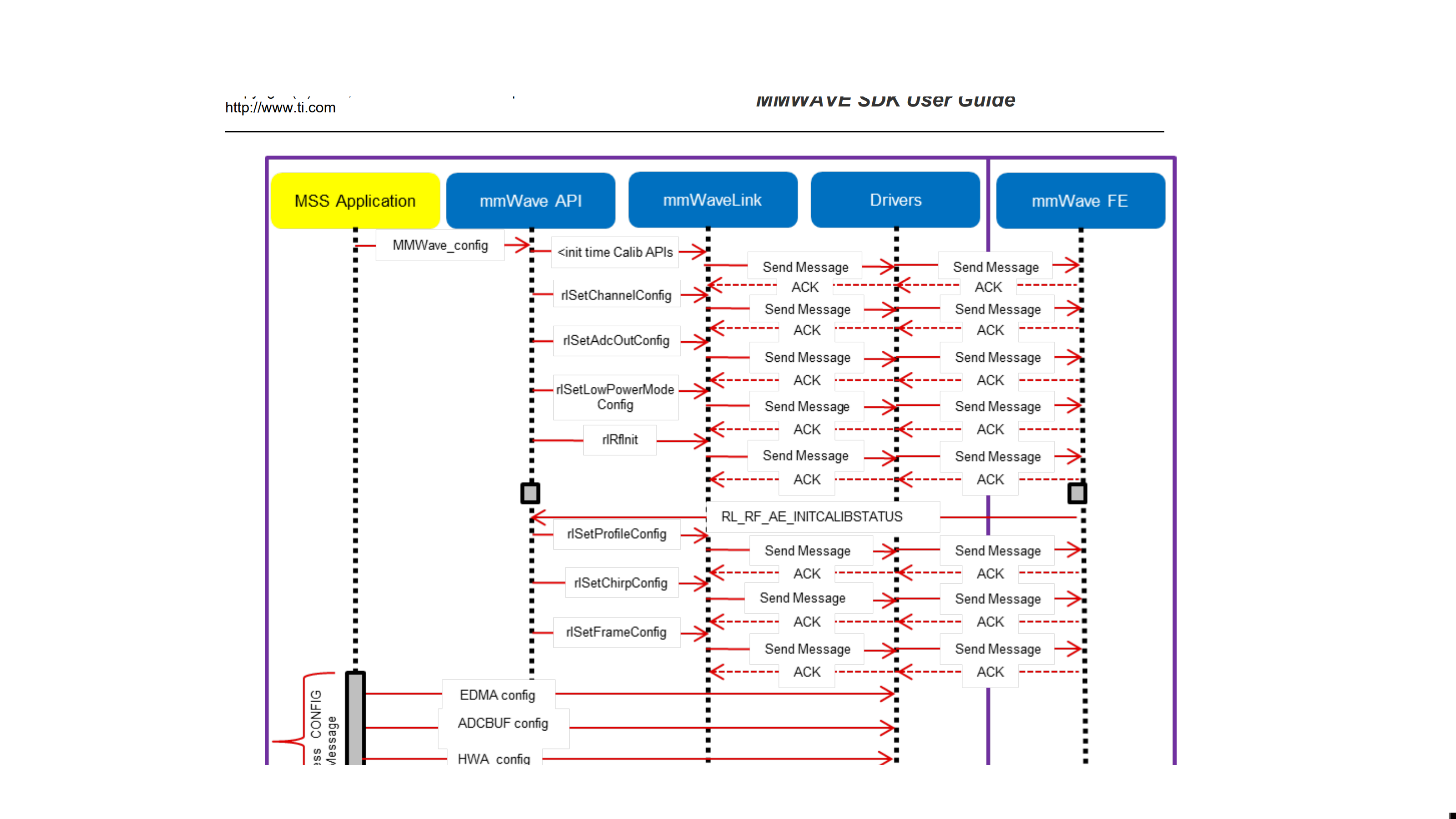
The image i have attached shows the sending of messages after configuring the channel and adc etc... Are we supposed to program this functionality in by using the function rlDriverSendMsg? If so what does it mean when its sending ACK back?

Thanks

  • Hello,

    As per mmWaveLInk protocol application or mmWave can invoke mmWaveLink APIs to configure radarSS frontEnd, where you can enable ACK for every command you send to frontEnd.

    The application doesn't need to bother or call any mmWaveLink internal functions, it just needs to call high-level APIs (as rlSetChannelConfig)  which is exposed to application to configure frontEnd.

    Let me explain one command in detail

    • Application calls mmWave API - MMWave_config
    • MMWave_config invokes mmWaveLink API 'rlRfInitCalibConfig'
    • mmWaveLink takes config parameters and generates command packet, which is forwarded to mailbox driver (in Picture it's named as Drivers).
    • mailbox driver copied command packet to radarSS mailbox so that radarSS read/process and acknowledge masterSS (in form of ACK packet) that command has been received by radarSS and processed without any error.
    • mmWaveLink will be blocked 'rlRfInitCalibConfig'' API till it receives ACK from radarSS.
    • After it receives correct ACK it returns to mmWave layer.

    Hope it clarifies your query.

    You can find details explanation of mmWaveLink protocol in Radar Interface Control document in mmWave-dfp package.

    Regards,

    Jitendra Gupta

  • Hi,

    Thanks for all your help but I'm a little confused on the order of the code. So far my code shows me configuring the API.  Surely the mailbox layer is programmed by us? After i've finished initialising the parameters then the mmwavelink takes config parameters and generates a command packet without me having to program it?

    #include <C:/ti/mmwave_sdk_01_00_00_05/packages/ti/control/mmwavelink/mmwavelink.h>
    #include <C:/ti/mmwave_sdk_01_00_00_05/packages/ti/control/mmwavelink/include/rl_driver.h>
    
    #include <stdint.h>
    #include <stdlib.h>
    #include <stddef.h>
    #include <string.h>
    #include <stdio.h>
    #include <math.h>
    
    void ADCInit();
    void ProfileInit();
    void ChirpInit();
    void ChannelInit();
    void FrameInit();
    void Radar();
    void LPMinit();
    
    int main(void)
    {
    
        rlRfInitCalConf_t InitCal;
        InitCal.calibEnMask = 4;
    
        ChannelInit();
        ADCInit();
        LPMinit();
        rlRfInit(RL_DEVICE_MAP_CASCADED_1);
    
        //rlDriverWaitForResponse(RL_DEVICE_MAP_CASCADED_1,);
    
        ProfileInit();
        FrameInit();
        ChirpInit();
        //rlSensorStart(RL_DEVICE_MAP_CASCADED_1);
    
    }
    
    void ChannelInit(){
    
        rlChanCfg_t ChanCfg = {0}; //channel configuration
        rlSetChannelConfig(RL_DEVICE_MAP_CASCADED_1, &ChanCfg);
        ChanCfg.rxChannelEn = 15; // Enabling 4 RX channels
        ChanCfg.txChannelEn = 7;  //Enabling 3 TX channels
        ChanCfg.cascading = 0; // cascading not needed
    }
    
    void ADCInit(){
    
        rlAdcOutCfg_t adcOutCfg = {0}; // ADC configuration
        rlSetAdcOutConfig(RL_DEVICE_MAP_CASCADED_1, &adcOutCfg);
        adcOutCfg.fmt.bitFormat.b2AdcBits = 0b10; // 16 bit ADC
        adcOutCfg.fmt.bitFormat.b2AdcOutFmt = 0b00; // use real output for ADC whereas using 01 will filter image band
    }
    
    void FrameInit(){
    
        rlFrameCfg_t frameCfg; // FMCW frame config
        rlSetFrameConfig(RL_DEVICE_MAP_CASCADED_1, &frameCfg);
        frameCfg.chirpStartIdx = 0;
        frameCfg.chirpEndIdx = 1;
        frameCfg.numLoops = 32;
        frameCfg.numFrames = 0; // infinite
        frameCfg.framePeriodicity = 4000000; // 20msec between each frame
        frameCfg.triggerSelect = 1; //SW API based triggering
        frameCfg.frameTriggerDelay = 0;
    }
    
    void ProfileInit(){
    
        rlProfileCfg_t profCfg = {0}; // configure one profile
        rlSetProfileConfig(RL_DEVICE_MAP_CASCADED_1,1U, &profCfg);
        //profCfg.profileId = 0;
        profCfg.startFreqConst = 0x558E38E3; //77GHz
        profCfg.idleTimeConst = 700; // time between two consecutive chirps
        profCfg.adcStartTimeConst = 300; // point of time in the chirps you want to sample the data to be processed by HWA
        profCfg.rampEndTime = 5800;
        profCfg.freqSlopeConst = 0x580; // 68Mhz/u sec
        profCfg.numAdcSamples = 225;
        profCfg.digOutSampleRate = 4500;
        profCfg.rxGain = 30; // 30dB
        //profCfg.txOutPowerBackoffCode = 0;
    }
    
    void ChirpInit(){
    
        rlChirpCfg_t chirpCfg[2U]; // initialise and use 2 chirps
        rlSetChirpConfig(RL_DEVICE_MAP_CASCADED_1, 2U, chirpCfg);
        chirpCfg[0].chirpStartIdx = 0;
        chirpCfg[0].chirpEndIdx = 0;
        chirpCfg[0].profileId = 0;
        chirpCfg[0].txEnable = 0; // transmit on channel TX0
    
        chirpCfg[1].chirpStartIdx = 1;
        chirpCfg[1].chirpEndIdx = 1;
        chirpCfg[1].profileId = 0;
        chirpCfg[1].txEnable = 4; // transmit on channel TX2
    }
    
    void LPMinit(){
        
        rlLowPowerModeCfg_t LPMcfg;
        LPM.anaChannelCfg = 0;
        LPM.lpAdcMode = 0;
        rlSetLowPowerModeConfig(RL_DEVICE_MAP_CASCADED_1,&LPMcfg);
    }

    Thanks for all your help