This thread has been locked.
If you have a related question, please click the "Ask a related question" button in the top right corner. The newly created question will be automatically linked to this question.
Hi ,
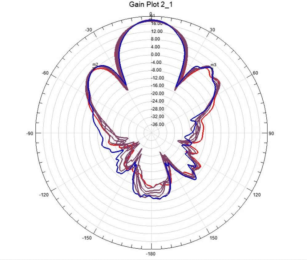
in the link below, it shows the azimuth gain of each RX1, RX2, RX3, RX4, TX1, and TX2.
https://e2e.ti.com/support/sensors/f/1023/p/665207/2458295#2458295
to calculate the link budget, which gain antenna receive/transmit I can use ? individual or as an array ?
Thanks
Regards
muhyin
7382.AWR1642_AWR1443_antennas_simulation2.pdfHello,
In the mmwave BOOST EVM User Guide, the per element antenna directivity gain is listed. Each Rx and Tx element has a per unit gain.
I have attached the simulation from the patch antenna designer.
The IWR1443 has 3Tx, 4Rx. The IWR1642 has 2Tx and 4Rx.
Regards,
Joe Quintal
Hi Joe,
I have simulated the antennas, and I can get per element antenna directivity gain similar to the ones you shared.
However, my question is related to radar equation/link budget and radar FOV (field-of-View). how to calculate the max range distance due to path loss, since you need gain TX and gain RX.
if the modulation scheme is BPM, Tx1 and TX2, transmit the power at the same time, would that be forming an array ? please see below my simulation of TX1+TX2 and RX1+RX2+RX3+RX4 as an array in azimuth plane.
should I use array gain of TX1 and TX2, instead of gain of per element antenna ?
Thanks
Regards
Muhyin
LevSen_RCS2_LinkBudgetCalc2_30mconfig2.xlsxHello,
in BPM MIMO swra554a, app note, the Transmitter power is higher. In the TDM MIMO it is the single Tx power. If you want to forward the simulation file, I can ask a system engineer more questions. If your simulation has the effective transmit power for BPM, you can use that.
In our use of the radar equation, active Tx transmit integrated time, chirp profile, we enter a system loss(2 db typical), and board losses (2db typical). We don't have a path loss term, we calculate for a given RCS, and Integrated-Tx time, we get the max range.
Please see the provided spreadsheet.
Regards,
Joe Quintal
Mmwave_webinar_Dec2017.pdfHi Joe,
could you please elaborate more on no path loss ? the signal will propagate through air, and i think should get some path loss. in attached TI document, page 15, it is shown there is.
when i select the rx number 4, the gain is increased. is this at bore sight 0 degree azimuth ? what is the gain, if the signal coming from angle 30,45 or 60 deg ?
Thanks and looking forward for your response
Regards
Muhyin
Hi Joe,
Could you please share the information of combine radiation pattern ?
especially at +-30 deg. as in our simulation. it indicates low gain, due to null on array 4 antenna RX .
Thank you very much.
Regards
Muhyin
Hello,
Normally we are limited to 2 simulateneous Tx, for BPM or TDM MIMO. These use the 4 Rx antennas. I do not have antenna pattern measurements for this case.
I will ask the other application engineers.
Regards,
Joe Quintal