This thread has been locked.

If you have a related question, please click the "Ask a related question" button in the top right corner. The newly created question will be automatically linked to this question.

AWR1243: Test pattern generation comparison between mmwave Studio and Wireshark

Part Number: AWR1243

Hello!

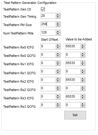
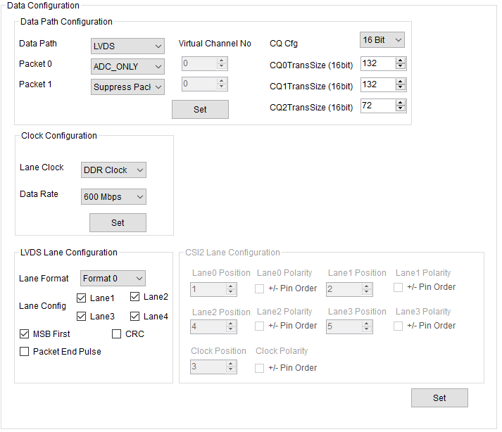
I am currently trying to receive a fixed pattern from the radar board, but it seems I am not getting the same pattern I configured on mmwaveStudio 1.0.0.0. I have attached the configuration I have used, knowing that my ADC sampling rate is 10MSps. I have left the offset field set to null, assuming that this configuration will just send first the pattern, and I have set the added values to I = FFFF and Q = 0000, respectively (to see the differences between the phases). Now, I expected to obtain on Wireshark some UDP packages containing just FFFF and 0000 all over, but I got nothing like I thought and commented when analyzing the first packages. I guess the configuration is not properly set, but I can not find too much documentation or guidance on configuring test pattern in mmwaveStudio. It would be helpful if you provide documentation on how to set these parameters or, at least, an example on how to configure the mmwaveStudio pattern generator and what we should expect as outcome on the UDP packages.

Thank you,

Gorka

  • Hi

    Could you please describe your setup. I am not clear where Wireshark comes into picture with AWR1243 EVM.

    Are you using the DCA1000 board to transfer Raw Data to a PC?

    Thank you
    Cesar
  • Hello,

    The setup is AWR1243 + DCA1000 evm. I wanted to set a specific pattern with mmwaveStudio and read it with Wireshark, this is, sniff the incoming traffic through Ethernet, but I did not succeed matching the test pattern generated above with the one obtained on Wireshark. If I am not wrong, the config above should give first packages filled with 0 and F, or? Could you please send some guide on how to specifically set the test pattern generator and what we should expect? I did not find anything about this in the documentation.

    I have attached more configuration details, in case you needed them to answer the question.

    Thank you,

    Gorka Iturbe


  • Gorka,

    This information comes from the Technical Reference Manual (TRM) for 14xx/16xx/18xx devices on the Test Pattern Generator:

    "An internal test pattern generator which outputs a ramp pattern helps during the initial software development and debug. The output of this module is muxed with the DFE data before sending it to the ADC buffers, as shown in Figure 13-2. Because this is meant for testing the path from the ADC buffer until the final output through LVDS, the ADC buffer configurations must be set to continuous streaming mode, in which the ping-pong switch is based on the number of samples. The test pattern generator can be configured by programming the register TESTPATTERNVLDCFG in the DSS_REG address space. Additional configurable registers are provided for configuring the ramp pattern output from the test pattern generator, such as offset at the start of ramp, step size, and so forth. Refer to the DSS_REG address space and test pattern generator-related registers for further information."

    Keep in mind that the test pattern generator values are muxed with the data from the DFE.

    Regards,
    Kyle
  • Hello Kyle,

    Before I check the explanation you suggested, is the manual valid for awr1243? I mean, I am not using either of the devices it explains about.

    Regards,
    Gorka
  • Gorka,

    Please refer to the documentation, specifically the Radar Interface Control Document that is included the mmWave DFP installation that can be found here: www.ti.com/.../MMWAVE-DFP

    Please refer to section 5.16.12 that is titled "AWR_DEV_TESTPATTERN_GEN_SET_SB".

    This documentation is valid for the AWR1243.

    Regards,
    Kyle