This thread has been locked.

If you have a related question, please click the "Ask a related question" button in the top right corner. The newly created question will be automatically linked to this question.

DRV5055: DRV5055 only reports two unique voltages ...no voltage change between the poles.

Part Number: DRV5055

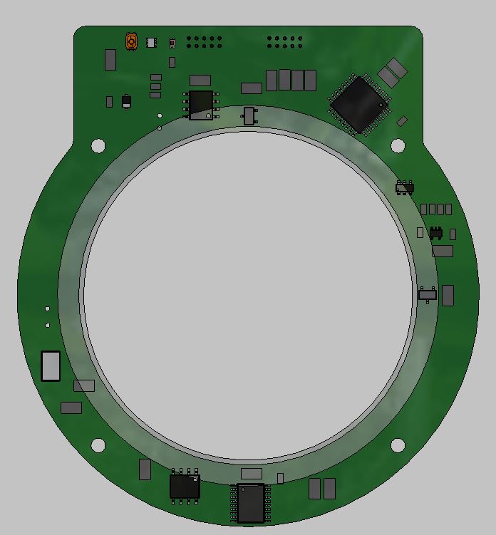
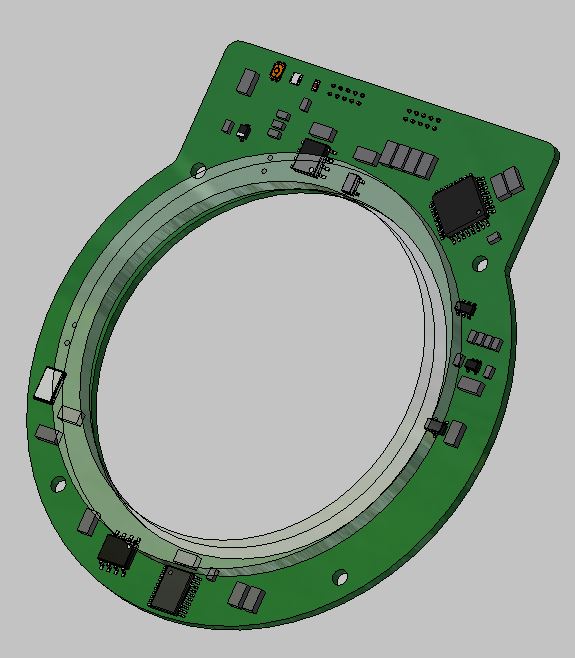
I'm designing a custom position sensor using two DRV5055A4QDBZR sensors 90 degrees apart.  

I'm using a custom ring magnet that has been diametrically magnetized.  I have the face of the ring magnet over the two sensors.  See image below from datasheet...except my magnet is a ring.

My sensors each only output two voltages.  As I rotate the magnet across the face of the sensor I expect to see a variable voltage yet I only ever get two unique values....approx. 2v and 3v...which suggest I need a different sensitivity.

Anyway, as a result my sensor can only calculate the 4 regions...not a continuous angle.

Any guidance is greatly appreciated.

  • Hello Anthony,

    Thank you for your question! Our engineers will analyze and respond when we return to the office tomorrow.

    Best regards,

    Ian Williams
    Applications Manager
    Current Sensing

  • Here is my package.  The air gap is approximately 0.035".  I don't know the flux density value for my magnet...I'm working with the vendor to sort that out.  To get started I selected the largest magnetic sensitivity range for the sensor.  perhaps this is my issue?

  • Hello Anthony,

    Thank you for using the TI forum.  From the images that you sent me, I see that the Hall sensor is placed almost directly under the center of the ring magnet band.  This is largely where the problem is coming from, as the direct center of the magnet band will have very little to no magnetic field in the direction the sensor is sensing.  To fix this, you should move the sensors out (away from the center hole) so that the farthest edge of the magnet passes halfway through the DRV5055 package, as in this image:

    (Note, the orientation of the sensors does not matter, just the physical placement because they sense magnetic field through the top of the package).

    This should significantly improve your output response, but you may still need to adjust which sensitivity version of the DRV5055 you are using based on the strength of the magnet.  This should be much easier to tell once the sensors have been re-positioned. 

  • Thanks. Is the sensor orientation critical? I have mine rotated 90 degrees from how you have them shown. Is half way overlapping optimal?
  • Hello Anthony,

    No, the sensor orientation is not critical, as the magnetic field passes through the top of the package (so your 90° rotation is fine).

    Yes, for your setup the optimal amount to have the edge of the magnet overlap the sensor is around the halfway point.

  • I made the change to the sensor location...unfortunately this didn't change the outcome.  I still get one high and one low voltage only.

  • Looks like I need to move the magnets even further out.  Does this make sense?

  • Hello Anthony,

    I'm not sure what you mean by "move the magnets even further out".  Did you mean sensors?  Having the sensors centered underneath the outer edge of the magnet is about where the field is strongest.  It is possible that you need a different device version.  The A4 you are using now has the highest range, but the lowest sensitivity.  

    I can better help with some more information on the magnet (so that I can run a simulation to help you find the correct device version).  To run this simulation, I need the exact dimensions of the magnet and the details for the magnetic material.  Specifically I need Br and Hc for the magnet (unless it is a very standard type, like Ceramic 8 for example).

  • Sorry, I meant sensors. The magnet is .125”x 2.475” OD x 2.135”ID. See data sheet. www.dropbox.com/.../plastalloy.JPG
  • I’m using the P1-A variety.
  • Whoops...P4.  Sorry.

  • Hello Anthony,

    I am having a hard time getting the datasheet from dropbox, can you attach the datasheet directly to a post? Or give a link to the datasheet online?

  • Also, I did switch to the lowest sensitivity sensor package.
  • Ok, thank you, that worked.  I'll run some simulations and get back to you on either Monday or Tuesday.

  • Great.  Hopefully you can get me something today.  I'm close to getting in a pickle with this thing.  :/

    FYI...I'm currently reading the sensors into an Atmega328 and doing the math for resolving the angle in that same chip.  I used the angle evaluation board source code.  My schematic is very simple.

    The outputs of the sensor head into an ADC on the micro.  Both sensors push 2.5v when the magnet is not  present.  When I install the magnet I get a nice full resolution swing that doesn't appear to be clipped.  

    To re-iterate...I'm using the most sensitive version on the sensor currently.  In general I get a high voltage when the sensor is under one pole then it switches and I get a low voltage on the other side of the pole...I seem to get not variation in output while rotating the magnet across the sensor.

    The label on my schematic is incorrect...I'm using DRV5055A1QDBZT currently.

  • Hey Anthony,

    I ran a simulation with the magnet specifications that you gave me, and with the sensor underneath the outer edge of the magnet and a sensor spacing height of 0.035in + 0.47mm (the 0.47mm is the distance from the top of the package to the sensing element).  From this simulation, it looks like the DRV5055A2 would work best for your situation.  However, this is subject small physical placement changes, so it is possible that the A1 or A3 work better based on the specific placements/tolerances.

    Looking at your last message, it appears that the main problem is not with the sensors/magnet placement, but with the MCU , and/or sampling frequency. You can confirm this by looking at the sensor output directly on an oscilloscope as you rotate the magnet by hand (or relatively slow with the motor, to make sure frequency is not an issue).  If the sensor output is still not looking correct in the oscilloscope with a relatively slow magnet rotation, then please send me the oscilloscope shots to help me further debug.  

    You mention in your previous email that "When I install the magnet I get a nice full resolution swing that doesn't appear to be clipped."  This sounds like you have already confirmed that the magnet/sensor setup is working properly, so I recommend looking at the MCU (and it's ADCs) to make sure that it can sample fast enough compared to the rotation speed of the magnet. 

    If you would like help selecting an MCU that would work for your specific setup, click either the "Ask a related question" or "Ask a new question" button, and the MCU team can help you out.  

  • So your simulation suggests that my placement and magnet strength should work?

    I'm confident that my ADC is not the issue as I'm doing these tests more or less static...I'm manually rotating the magnet.  I do not believe it's frequency related.

    As a test I dramatically adjusted the air gap.  This greatly lowered my voltage response but at least yields a signal that I can process into angle sort of.

    However this very large air gap isn't practical.

  • In my mind moving the sensors further out would be equivalent or similar to this larger air gap.  Does your simulation provide any dimensional placement info?

  • Here is a screen cap of my ADCs while slowly hand rotating the magnet.  I have the air gap set to about 0.200".

    I get a transition where the magnet switches from north to south pole...this is also physically marked on my magnet...but as you can see I get a relatively constant output while either the north or south pole are above the magnet.

    This isn't saturation.

    Maybe I'm confused and this is the correct output behavior of this device?

    I've also re-read through the different technical docs...I see mention of "ring magnets" in Section 2.2 of the Linear Hall Effect Sensor Angle Measurement Theory, Implementation, and Calibration paper.  However none of the examples show a ring magnet being used?  

    Is my ring shaped magnet the culprit here?  Or more likely....is my magnet not magnetized how I think it should be??

  • Okay...some of my confusion can be put to rest.

    These magnets are not diametrically magnetized like I thought....they have two poles on each face....so it makes some sense that I get a constant magnetic flux density under the entire north and/or south pole.

    I'm trying to solve this but finding the correct magnet will likely be a challenge.

    Solved for now.

  • Hello Anthony,

    I'm glad you were able to figure out your problem.  

    In terms of finding a new magnet, I have a couple ideas for you:

    1)  I know that Phoenix America (https://www.phoenixamerica.com) does custom magnets (from a molded compound) so I'm sure you could get something there that works.  Not sure if the cost will work for you or not though. 

    2) Some customers will put a gear around their central rotating axis, and have that gear spin another gear with a smaller/cheaper magnet on it.  Then they'll use the smaller magnet to get the info they need.  This may not quite work for your space requirements though...  (you would need to make sure that the magnet spins the same rate as your motor.....)