


Other Parts Discussed in Thread: AWR1642BOOST
Hi,
I am working on my own software to process the raw data from the mmWave sensor. However, the range results from Radar Studio are different from Matlab FFT. The error is not consistent which makes me wonder if there is some calibration needed to the raw data before processing it. Any ideas about that?
On a related topic, the results I get are obtained from the FFT of REAL raw data (fft(real(data))). This puzzles me because, from my understanding, the complex raw data is the actual waveform information at the Rx so only using the real component should not yield any sensible results. Applying FFT to the complex data results in even worse results without any peak (target detected). So I presume that the data needs some pre-processing.
Hardware: AWR1642BOOST, MMWAVE-DEVPACK, TSW1400EVM
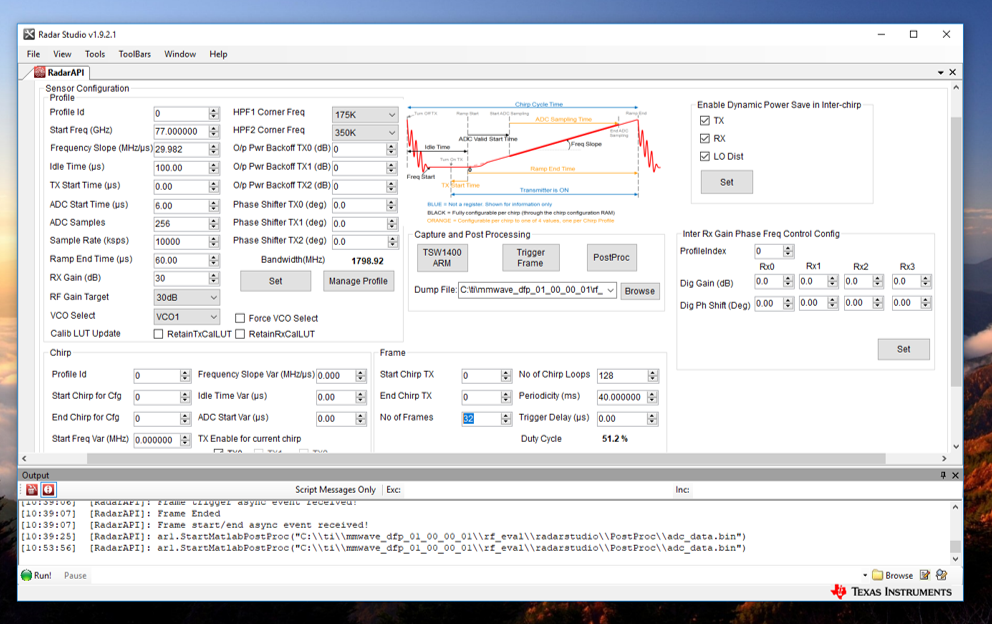
Configuration:
Error:
| Real Distance (m) | Radar Studio Distance (m) | Matlab FFT distance (m) |
| 0.44 | 0.585 | 0.33 |
| 0.91 | 0.975 | 0.498 |
| 1.49 | 1.56 | 0.75 |
| 2.4 | 2.9 | 1.7 |
Matlab code:
data = readTSA1400('adc_data_18in_0.6m.bin');
[n,c] = size(data); %n = #receivers
N_DAC = 256; %number of samples per chirp
N_CHIRPS = c/N_DAC; %number of chirps
CHIRP_TIME = 60e-6; %time for chirp
B = 1.79892e9; %effective bandwidth
CHIRP_SLOPE = B/CHIRP_TIME; %slope of frequency
Ts = CHIRP_TIME / (N_DAC-1); %effective IF sampling rate
Fs=1/Ts; %IF sampling freq
Nfft = N_DAC*1; %zero-padding for fft
t = linspace(Ts,CHIRP_TIME,N_DAC); %time vector for a single chirp
t_chirps = 0:CHIRP_TIME:(N_CHIRPS-1)*CHIRP_TIME; %start of each chirp
df = Fs/Nfft;
f = (-Fs/2+df):df:(Fs/2); %frequency vector
range = f.*3e8./2/CHIRP_SLOPE; %range vector
range = range(f>0);
MAX_RANGE_PLOT = 4; %in m, change this to change image max range
MAX_RANGE = Fs/2 * 3e8 / 2 / CHIRP_SLOPE; %maximum range from IF BW
RANGE_RES = 3e8/2/B; %range resolution
chirp=1; % chirp selector
X=data(1,256*(chirp-1)+1:256*chirp)'; % Input vector to apply FFT
T = 1/Fs; % Sampling period
L = size(X,1); % Length of signal
L=2^nextpow2(L);
t = (0:L-1)*T; % Time vector
Y=fft(real(X),L);
P2=abs(Y/L);
P1=P2(1:L/2+1);
P1(2:end-1)=2*P1(2:end-1);
f=Fs/L*(0:(L/2));
hold on
figure
plot(f,20*log(P1))
plot(range,20*log(P1))
