This thread has been locked.

If you have a related question, please click the "Ask a related question" button in the top right corner. The newly created question will be automatically linked to this question.

FDC2214: Non-conductive surface touch

Part Number: FDC2214
Other Parts Discussed in Thread: TIDA-00466, TIDA-00464, , FDC2114

Dear team, 

The customer checked our reference design of TIDA-00466. but the customer consider using non-conductive surface like glass and they want to know whether they can use FDC series or not. Is this available to detect with or without only fingers? 

- Application : finger touch system on glass 

- Thickness of glass : 12mm 

please let me know your opinion regarding this application and if there is a design touch system using non-conductive surface.   

 Thank you. 

  • Hello,

    Yes, this is possible with the FDC devices. Please see this reference design: http://www.ti.com/tool/TIDA-00464

    Best Regards,

  • Hello Jones, 

    Thank you for your support. As your recommendation, we are promoted TIDA-00464 and the customer are conducting test using this EVM. 

    Regarding this Design, there are some questions. please review below question and let me know your opinion. 

    <Sensing distance> 

    1.  Button 1,2 on TIDA-00464, the customer want to have more sensing distance with same sensor size. Is there a way to increase the sensing distance other than changing the sensor size like changing cap value ,sensor pattern change, inductance change or changing register value of FDC2214?   

    2. At user guide, We can see below mention. but I can confused about the GND system. 

    "The maximum sensing distance that can be reliably achieved with the board is 10 cm (4 inches) as a floating system and 50 cm (19.6 inches) as a grounded system"

    If there is the system  between EVM powered by AA battery and human body finger, Is this system is a floating system or a grounded system?

    Once this system is a floating system, how can i configure a grounded system? Can I connect EVM power to a wall outlet? 

    3. Regarding Shield : At datasheet 10.1.2 of FDC2114, "actively driven shield: The shield is a buffered signal of the INxA pin. The signal is buffered by an external amplifier with a gain of 1."

    Is this mean If we add external amplifier with unit gain in front of INxA, external amp can help in order to minimize interference? please let me know how can i design external amp for reducing interference. 

    4.  lock up after Reset button(soft reset) : After pushing reset button, sometimes a system lock up occurs. If this lock up occurred, POR only can release this lock up. please let me know your opinion on the possibility of this problem occurring. 

    Thank you. 

  • Dear Kristin, 

    I am sorry to push you but Is there any update on this request? 

    Thank you. 

  • Hello Dino,

    1. Some of the register setting can affect resolution, but only the electrode size determines the sensing distance.

    2. The difference between floating and grounded systems is discussed in more detail in section 2.1 of the user's guide. If the EVM is powered by a battery, then it is a floating system. You could turn it into a grounded system by connecting it to a laptop which is connected to a wall outlet. 

    3. Please see this E2E post for more information about active shielding: https://e2e.ti.com/support/sensors/f/1023/t/802488#pi320995=2

    4. Can you clarify what you mean by a system lock up? How is the EVM behaving?

    Best Regards,

  • Hello Kristin, 

    Thank you for your reply. And I am sorry for confusing. 

    The customer are testing TIDA-00466 EVM(Noise-immune Capacitive Proximity Sensor System Reference Design) not TIDA-00464 as you recommend 

    1. Done

    2. Done

    3. I checked other E2E post but I can not understand clearly. Is there reference design with active shielding? How can I select and design Op amp as a buffer? 

    This is not issue yet but please let me know again. 

    4. At TIDA-00466 EVM(Noise-immune Capacitive Proximity Sensor System Reference Design),

       There is reset button. After push reset button, the EVM is not operating sometimes. Only after POR is done will it function normally.

    Thank you    

  • Hello Dino,

    3. We do not have a reference design that uses active shielding. Please see page two of the e2e post I shared, which gives a recommended op amp and schematics for active shielding.

    4. Can you explain in more detail how the EVM is not operating? Are the LEDs not lighting up? 

    Best Regards,

  • Hello Kristin, 

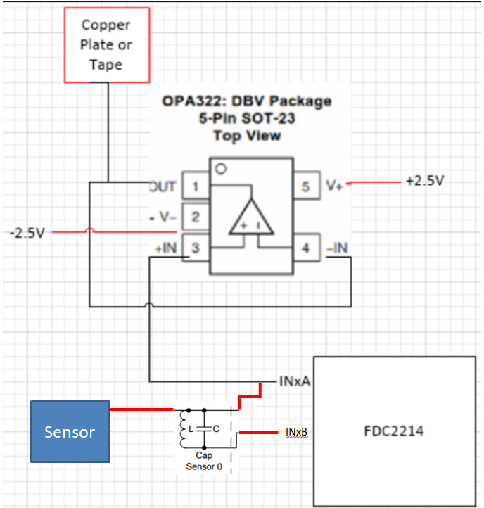
    I am sorry to bother you but please review one more regarding active shield. I revised your block as your recommendation like below. 

    Is the below block correctly applied your recommendation? 

    1. It should be in parallel with the sensor => Is it right?

    2. It should only be connected to the output of the amplifier => Is it right?

    3. It should be the same size as the sensor plate  

    4. It should be located very close to the sensor plate.

       => Where do you think it's better to be located for better performance? same layer or other layer? 

    Thank you. 

  • Hello Dino,

    1-3 are correct. However, the shield electrode location you've drawn will not effectively shield the sensor electrode. The shield and the sensor need to be in the same (x,y) location but on different layers of the board. Figure 3 in this application note shows how the sensor and shield electrodes should be located.

    Best Regards,