This thread has been locked.

If you have a related question, please click the "Ask a related question" button in the top right corner. The newly created question will be automatically linked to this question.

TMP422-Q1: Reading all three temperatures of the TMP422-Q1 registers

Part Number: TMP422-Q1
Other Parts Discussed in Thread: TMP422, DXP

Dear Support Team,

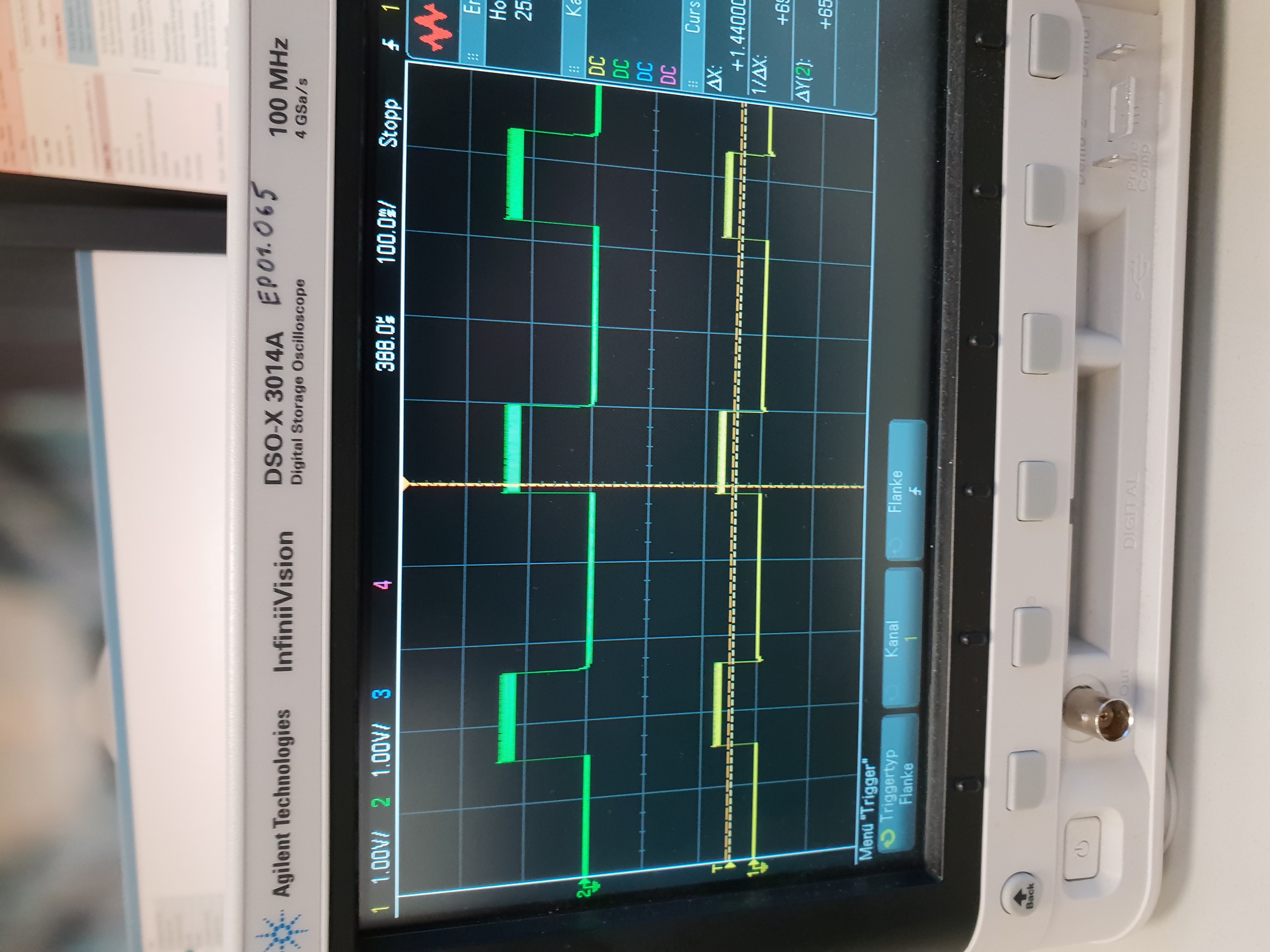
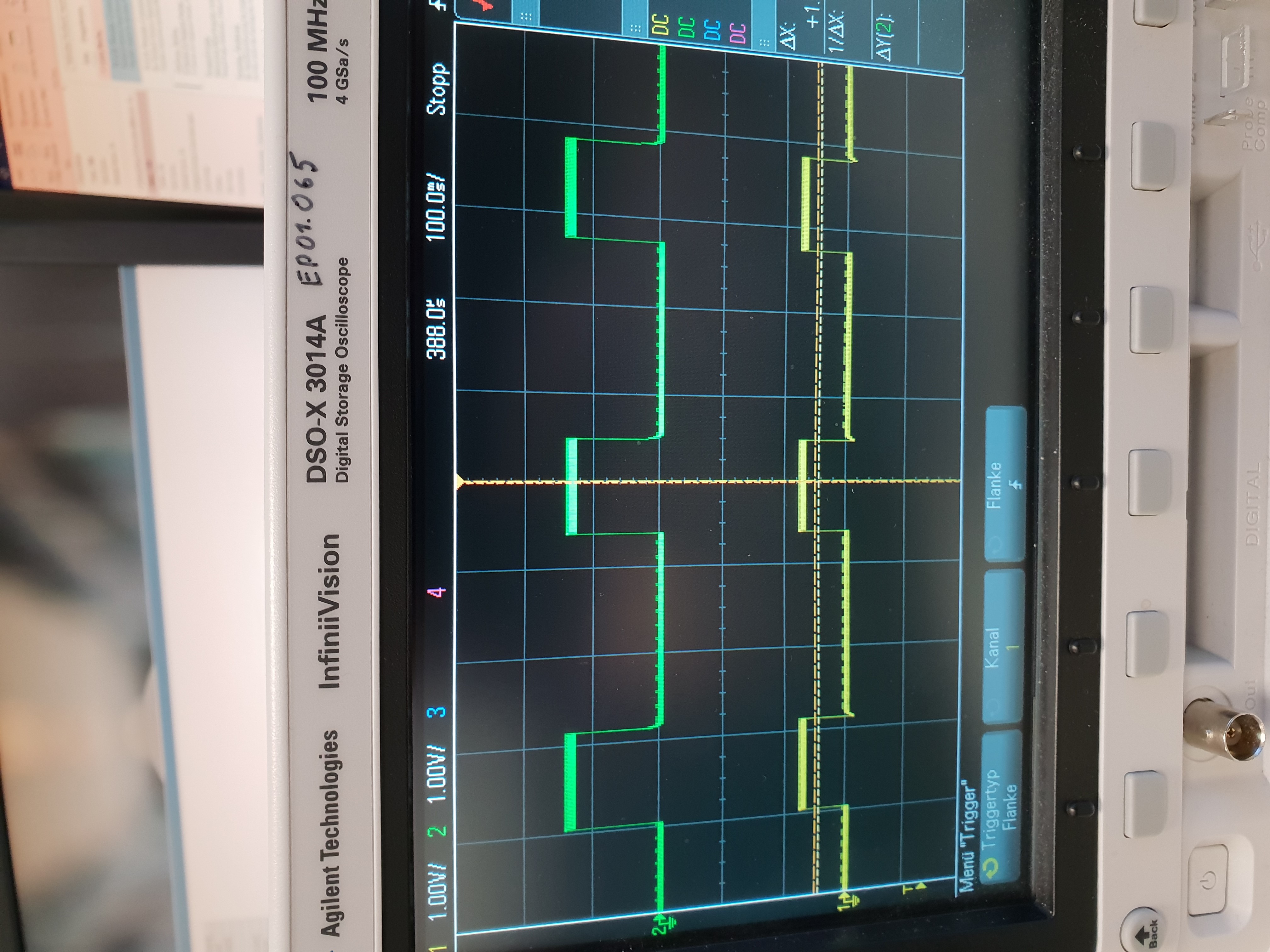
I try to read the local, remote1 and 2 temperatures via I2C from the TMP422-Q1 register values with a STM32 microcontroller.

Below, my timing configurations can be found. 

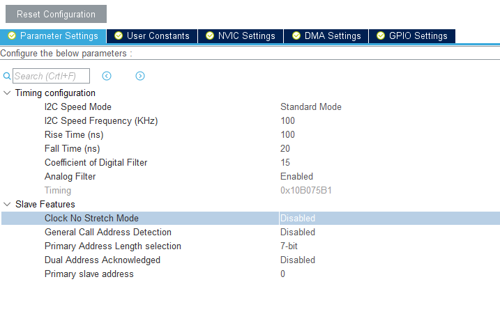
Below, my Code can be found: 

/* SCAN i2C adresses */

HAL_Delay(500); 

for( uint8_t i =0; i <255; i++)

{

if(HAL_I2C_IsDeviceReady(&hi2c2, i, 1, 10) == HAL_OK)

{

a[cnt] = i; 

cnt ++;

}

}

// Set Conf Reg 2 of external TMP422 sensor 

uint8_t CNF_RGY_2_Tx[2];

CNF_RGY_2_Tx[0] = CNF_RGY_2;

CNF_RGY_2_Tx[1] = CNF_RGY_2_SETUP;

if ( HAL_I2C_Master_Transmit(&hi2c2, 0x98, CNF_RGY_2_Tx, 2, 100) == HAL_OK )

{

while (HAL_I2C_GetState(&hi2c2) != HAL_I2C_STATE_READY)

{

cnt = 1;

}

}

// Get Conf Reg 1 of external TMP422 sensor

if ( HAL_I2C_Master_Transmit(&hi2c2, 0x98, &CNF_RGY_1, 1, 100) == HAL_OK )

{

while (HAL_I2C_GetState(&hi2c2) != HAL_I2C_STATE_READY)

{

cnt = 2;

}

if ( HAL_I2C_Master_Receive(&hi2c2, 0x99,(uint8_t *) I2CRx_CNF_RGY_1, 1, 100) == HAL_OK )

{

while (HAL_I2C_GetState(&hi2c2) != HAL_I2C_STATE_READY)

{

cnt = 3;

}

}

}

// Get Conf Reg 2 of external TMP422 sensor

if ( HAL_I2C_Master_Transmit(&hi2c2, 0x98, &CNF_RGY_2, 1, 100) == HAL_OK )

{

while (HAL_I2C_GetState(&hi2c2) != HAL_I2C_STATE_READY)

{

cnt = 4;

}

if ( HAL_I2C_Master_Receive(&hi2c2, 0x99,(uint8_t *) I2CRx_CNF_RGY_2, 1, 100) == HAL_OK )

{

while (HAL_I2C_GetState(&hi2c2) != HAL_I2C_STATE_READY)

{

cnt = 5;

}

}

}

  /* USER CODE END 2 */

  /* Infinite loop */

  /* USER CODE BEGIN WHILE */

  while (1)

  {

// Get Local Temp 

if ( HAL_I2C_Master_Transmit(&hi2c2, 0x98, &PTR_RGY_0, 1, 100) == HAL_OK )

{

while (HAL_I2C_GetState(&hi2c2) != HAL_I2C_STATE_READY)

{

cnt = 6;

}

if ( HAL_I2C_Master_Receive(&hi2c2, 0x99,(uint8_t *) I2CRx_LOC, I2C2_RX_FieldSize, 100) == HAL_OK )

{

while (HAL_I2C_GetState(&hi2c2) != HAL_I2C_STATE_READY)

{

cnt = 7;

}

// Only quick and dirty 

if ( I2CRx_LOC[0] >= 0xC0 ) {

TempLoc = -256 + I2CRx_LOC[0] - (double) I2CRx_LOC[1]/256; 

}else{

TempLoc = (double) I2CRx_LOC[0] + (double) I2CRx_LOC[1]/256;  

}

// Error Analysis 

if ( TempLoc == -64 ) {

KS_TLOC = 1; 

}

if ( I2CRx_LOC[0] & 0x01 ) {

OK_TLOC = 1; 

}

}

}

// Set PTR Register to remote 1 and receive Data

if ( HAL_I2C_Master_Transmit(&hi2c2, 0x98, &PTR_RGY_1, 1, 100) == HAL_OK )

{

while (HAL_I2C_GetState(&hi2c2) != HAL_I2C_STATE_READY)

{

cnt = 8;

}

if ( HAL_I2C_Master_Receive(&hi2c2, 0x99,(uint8_t *) I2CRx_DSP, I2C2_RX_FieldSize, 100) == HAL_OK )

{

while (HAL_I2C_GetState(&hi2c2) != HAL_I2C_STATE_READY)

{

cnt = 9;

}

// Only quick and dirty 

if ( I2CRx_DSP[0] >= 0xC0 ) {

Temp = -256 + I2CRx_DSP[0] - (double) I2CRx_DSP[1]/256; 

}else{

Temp = (double) I2CRx_DSP[0] + (double) I2CRx_DSP[1]/256;  

}

// Error Analysis 

if ( TempLoc == -64 ) {

KS_TR1 = 1; 

}

if ( I2CRx_DSP[0] & 0x01 ) {

OK_TR1 = 1; 

}

}

}

if ( HAL_I2C_Master_Transmit(&hi2c2, 0x98, &PTR_RGY_2, 1, 100) == HAL_OK )

{

while (HAL_I2C_GetState(&hi2c2) != HAL_I2C_STATE_READY)

{

cnt = 10;

}

if ( HAL_I2C_Master_Receive(&hi2c2, 0x99,(uint8_t *) I2CRx_DSP2, I2C2_RX_FieldSize, 100) == HAL_OK )

{

while (HAL_I2C_GetState(&hi2c2) != HAL_I2C_STATE_READY)

{

cnt = 11;

}

// Only quick and dirty 

if ( I2CRx_DSP2[0] >= 0xC0 ) {

Temp2 = -256 + I2CRx_DSP2[0] - (double) I2CRx_DSP2[1]/256; 

}else{

Temp2 = (double) I2CRx_DSP2[0] + (double) I2CRx_DSP2[1]/256;  

}

// Error Analysis 

if ( TempLoc == -64 ) {

KS_TR2 = 1; 

}

if ( I2CRx_DSP2[0] & 0x01) {

OK_TR2 = 1; 

}

}

}

    /* USER CODE END WHILE */

    /* USER CODE BEGIN 3 */

  }

  /* USER CODE END 3 */

}

The TMP is connected in such a way, that the adress should be 0x98 / 0x99, depending on the read/write value. These adresses are found by my Code, so that seems to be right.

I manage to read the local and remote 1 temperature values, the remote 2 temperature values are frozen however. The result seems to be an open circuit. If I force a short circuit, the value also changed to the right short circuit value -64. 

I just wanted to clarifiy, that there are no timing issues / software mistakes and the error seems to be hardware related. 

Thank you and kind regards

Sebastian 

  • Sorry, these are my predefined variables: 

    /* Private define ------------------------------------------------------------*/
    /* USER CODE BEGIN PD */
    #define I2C2_RX_FieldSize ((uint8_t ) 2)

    /* USER CODE END PD */

    /* Private macro -------------------------------------------------------------*/
    /* USER CODE BEGIN PM */

    /* USER CODE END PM */

    /* Private variables ---------------------------------------------------------*/

    I2C_HandleTypeDef hi2c2;

    /* USER CODE BEGIN PV */

    /* USER CODE END PV */

    /* Private function prototypes -----------------------------------------------*/
    void SystemClock_Config(void);
    static void MX_GPIO_Init(void);
    static void MX_I2C2_Init(void);
    /* USER CODE BEGIN PFP */

    /* USER CODE END PFP */

    /* Private user code ---------------------------------------------------------*/
    /* USER CODE BEGIN 0 */
    uint8_t a[10] = {0};
    uint8_t cnt = 0;

    uint8_t I2CRx_LOC[I2C2_RX_FieldSize] = {0};
    double TempLoc = 0;

    uint8_t I2CRx_DSP[I2C2_RX_FieldSize] = {0};
    double Temp = 0;

    uint8_t I2CRx_DSP2[I2C2_RX_FieldSize] = {0};
    double Temp2 = 0;

    uint8_t I2CRx_CNF_RGY_1[1] = {0};
    uint8_t I2CRx_CNF_RGY_2[1] = {0};

    uint8_t PTR_RGY_0 = 0x00;
    uint8_t PTR_RGY_1 = 0x01;
    uint8_t PTR_RGY_2 = 0x02;

    uint8_t CNF_RGY_1 = 0x09;
    uint8_t CNF_RGY_2 = 0x0A;

    uint8_t CONVRATE_RGY = 0x0B;

    uint8_t CNF_RGY_2_SETUP = (0x1F << 2); //(0xF << 2); // Activate all possible channels + Resistance correction enable

    _Bool KS_TLOC = 0;
    _Bool KS_TR1 = 0;
    _Bool KS_TR2 = 0;

    _Bool OK_TLOC = 0;
    _Bool OK_TR1 = 0;
    _Bool OK_TR2 = 0;

  • Hi Sebastian,

    The timing settings look okay, but without an oscilloscope waveform I cannot confirm all the timings are executed correctly.
    What hex values are you getting for your local, remote 1 and remote 2 temperatures? Does your result seem to be an open on the local as well?

    You can also check the DXP pin to see if their is a signal for the different current injections.

    Can you send me a schematic for reference?

    Thanks,

  • Hi Sebastian,

    Have you made any progress on this concern?

    Thanks,

  • Closing this thread because of inactivity.  Feel free to reopen this post or create a new one if you need further assistance.

    Thanks,

  • Hello David,

    sorry for the late response.

    The hex values for the local temperature are:   0x21  and 0x70 => 33.4375°C. These values also change, if I try to heat the system up a bit. 

    The hex values for the remote 1 temperature are: 0x23 - 0x24 and 0x10- 0xB0. => ~ 35-37 °C. These values also change according to an applied heat source. 

    The hex values for remote 2 temeprature are: 0x09 and 0x0A which should be an Open. 

    I tested these on 3 different, identically build boards to ensure that I have at least one functional sensor. On all three boards, the remote 2 temperature seems frozen.  

    Below, the schematic can be seen: 

    The DSP1/2_THD+/- signals are then fed directly to the corresponding DSP diodes. It seems to work perfectly fine with DSP1, but not with DSP2 unfortunately. DSP2 is located 10cm further away from the TMP422 sensor then DSP1, which is the only difference. 

    I didn't understand your comment about the DXP pin. 

    Thank you and kind regards

    Sebastian 

  • I was also able to measure the injection signals from the TMP422 directly at the corresponding DSP2 pins. If i shortcut the DSP pins, the value changes to -64°C , which seems to be right. .. 

  • Hi Schoeli,

    Can you send me a oscilloscope waveform of the DX3 and DX4 pins?

    Thanks,

  • Hello David,

    below, the wafeforms for DX3 and DX4 can be found. Green should be DX3 and yellow DX4. 

    In comparison, DX1 and 2 can be seen below. I can't seem to make a difference and I was also able to measure these signals directly at the corresponding DSP pins. 

    Thank you for your help and kind regards

    Sebastian 

  • Hi Sebastian,

    The waveforms should be okay.  I am skeptical of the values 0x09 and 0x0A for your remote 2 temperature read. Is the MSB and 0x09 and and LSB 0x0A?  This would indicate a UVLO which would be set on the remote LSB as well.  These are also your values for uint8_t CNF_RGY_1 = 0x09; and uint8_t CNF_RGY_2 = 0x0A, but this could just be a coincidence. 

    Can you check the I2C traffic when reading the remote 2 temperature to make sure it is staying at a consistent  0x09,0x0A?

    Thanks,

  • Hi David,

    Indeed, I think ( and have already stated in a previous message ), that it indicates a UVLO. The values for the CNF_RGY are taken of the Data sheet of your device. 
    The values are staying consistend 0x09, 0x0A. If i shortcut the Pins, either at the DSP2 or the TMP, the values change to the corresponding short cut value that are given in the data sheet.

    The only possible explanation would be, that the DSP2 might not be correctly soldered on the pad, if the signals and the timings of the I2C bus seem to be fine? 

    Kind regards

    Sebastian 

  • Hi Sebastian,

    Can you check the I2C traffic when reading the remote 2 temperature?

    Thanks,

  • Hi Sebastian,

    Did you get the chance to get the I2C traffic waveforms of the remote 2 temperature register read?

    Thanks,

  • Closing this thread because of inactivity.  Feel free to reopen this post or create a new one if you need further assistance.

    Thanks,

    David