This thread has been locked.

If you have a related question, please click the "Ask a related question" button in the top right corner. The newly created question will be automatically linked to this question.

LDC1314-Q1: sporadic outliers on DATA_CHx (LDC1314-Q1)

Part Number: LDC1314-Q1
Other Parts Discussed in Thread: LDC1314

on some parts I observe sporadic outliers on one ore more DATA_CHx channels.

The value for DATA_CHx then jumps to 4095 for 1 sample while before and afterwards the values are ok.

There are parts not showing any issues, other where 1 channel is affected and I have also seen a part with 2 channels showing this.

The system is operating at room temperature with the object in the normal detection range.

The deglitch filter is set correctly to the lowest value above the resonant frequency.

The amplitude has been checked and is within the expected range.

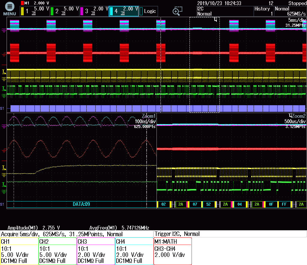
The scope plot illustrates the issue:

Trigger is activated when DATA_CH0 = 0x0FFF (4095) is transmitted. (zoomed portion lower right side)

You can also see that the measurement before this transmission didn't happen correctly.

CH3 / CH4 are probing the CH0_A / CH0_B and M1 is the calculated difference.

In the zoomed picture left right you can see the normal amplitude in one of the successful measurements before.

Any ideas what this issue could be caused by?

best regards,

Martin

  • Hello Martin,

    I'm sorry you are experiencing this issue. Can you share what setting you are using for the DRIVE_CURRENT registers? In addition, have you measured the Rp of your sensor? If you do not know how to do so, this application note should help you. 

    You also mentioned that this behavior varies across parts. Have you tried swapping the parts between boards to see if the behavior follows the part or the board?

    Best Regards,

  • Kristin,
    thank you for your response.

    Rp measurements are initiated, I hope to get results soon. With the calculation tool we got a value of 3.84kOhm (without target interaktion).

    Please see below our register settings {address, data}:

    .ldc1314_init_data =
    {
    {0x08, 0x03E8},
    {0x09, 0x03E8},
    {0x0A, 0x03E8},
    {0x0B, 0x03E8},
    {0x0C, 0x7148},
    {0x0D, 0x7148},
    {0x0E, 0x7148},
    {0x0F, 0x7148},
    {0x10, 0x0040},
    {0x11, 0x0040},
    {0x12, 0x0040},
    {0x13, 0x0040},
    {0x14, 0x1004},
    {0x15, 0x1004},
    {0x16, 0x1004},
    {0x17, 0x1004},
    {0x19, 0x0000},
    {0x1A, 0x1C00},
    {0x1B, 0xC20D},
    {0x1C, 0x0400},
    {0x1E, 0xD800},
    {0x1F, 0xD800},
    {0x20, 0xD800},
    {0x21, 0xD800},
    },

    In the meantime I've tried to get a little bit more information out of the LDC1314 by enabling the error-mapping to the output registers (0x19 = 0xF800).

    Now I get 0x5FFF in case of errors, means CHx_ERR_OR + CHx_ERR_AE

    best regards,

    Martin

  • Hi Martin,

    Thank you for the additional information. Please update me when you have Rp measurements available, as well as the part-swap tests.

    In the meantime I will look over your register settings.

    Best Regards,

  • Kristin,
    our Rp measurements show actual values of 1.25kOhm (calculated 3.84kOhm) with no target interaction.
    With target interaction and with increasing temperature, I would assume to get even lower values.

  • Hi Martin,

    I've just sent this response to Jon, but I'll post it here as well. 

    It’s very likely to me that the missing samples are due to the sensor Rp being too low for the LDC to drive. I have only seen this issue caused by the sensor Rp and drive current settings.

    A quick fix to test this theory is to reduce the sensor capacitance to increase the Rp. If you have measured their sensor Rp using an impedance analyzer or network analyzer, then you can just look at the Rp value across frequency. If the Rp value increases above 1 kΩ (WITH the target) at a certain frequency, then you can select the corresponding capacitor to set the sensor frequency accordingly. Unfortunately your sensor frequency is already quite high with the target present, so you may run into the upper frequency bound of the device (10 MHz).

    If you cannot solve the issue by changing the sensor capacitor, you’ll need to make changes to their coil. The quickest fix would be to add additional layers if this is an option. Decreasing the trace spacing and increasing the number of turns would also help. They can also consider adding a series SMD inductor. I’d be happy to discuss any of these options in more detail if needed.

    In answer to your question, the Rp will definitely decrease with target interaction and with increasing temperature.

    Best Regards,

  • Kristin,
    thank you for the response.


    I agree, changing the capacitor will bring the system near to the upper bounds.
    Changing the coils is not possible due to geometry / space constraints

    Adding an SMD inductor could be an option since we have foreseen a 0402 placeholder in the design.
    Any suggestions on sizing the inductor from your side?

    best regards,

    Martin

  • Hi Martin,

    I suggest that you measure the coil’s inductance with the target present, then size the series inductor so that the sensor Rp value meets the minimum 1 kΩ with some padding. A minimum of 1.5 kΩ would be okay, but 2 kΩ would be more robust. You’ll need to account for the series inductor’s tolerances when you calculate the Rp, which is one of the disadvantages to this option. You’ll see more significant variation in the output data from board-to-board because of the series inductor’s tolerance and will need to account for this in their detection algorithm. This shouldn’t change the response from the target, just the offset of the output codes. In addition, the wire-wound inductors often have lower self-resonant frequencies. You’ll need to make sure that their sensor frequency is less than 75% of this frequency.

    Best Regards,