This thread has been locked.

If you have a related question, please click the "Ask a related question" button in the top right corner. The newly created question will be automatically linked to this question.

IWR6843: For IWR6843 ISK z-axis data

Part Number: IWR6843

Dear TechnicalSupport

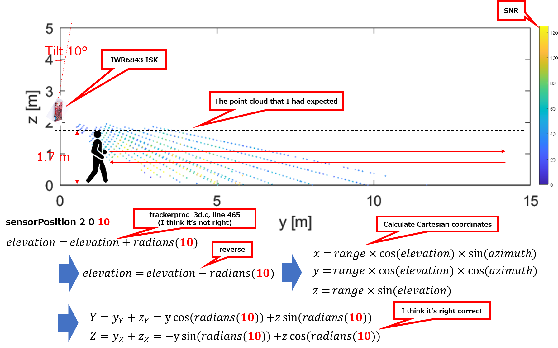
I use IWR6843 ISK(ES2.0) following FW was burned.

C:\ti\mmwave_industrial_toolbox_4_2_1\labs\people_counting\68xx_3D_people_counting\prebuilt_binaries\3D_people_count_68xx_demo.bin

Install the radar at a height of 2.5m as shown below.
I walked a distance of 15m from right below in the y-axis direction.
The result is that the point cloud looks above the person's head.
Is there any correction applied to the z-axis direction?

Also, in 3D People Counting in TI Resource Explorer
The name of the folder is ODS.
But, In the user guide, the supported device is written as ISK.
Is it correct that I can use it for both ODS and ISK?

I plan to use the below FW in the future, but I would like to check the validity of the data I have acquired.

C:\ti\mmwave_industrial_toolbox_4_2_1\labs\long_range_people_detection\68xx_long_range_people_det\prebuilt_binaries\long_range_people_det_68xx_demo.bin

Best Regards

  • Hi User,

    This lab supports both ISK and ODS. There is point cloud correction being done - the sensor is given an azimuth tilt (with respect to wall behind it) and an elevation tilt (with respect to the ground). By default, the sensor is assumed to be downtilted 15 degrees, so point cloud is shift 15 degrees up.  If the device is not tilted down in your test, points should appear above the person, and get farther above the person as the person gets farther from the device.

    You can change the downtilt setting in the gui - see the sensor position arguments on the bottom left panel.

    Regards,

    Justin

  • Dear Justin

    Thank you for your reply.

    To correct point cloud is in GUI software isn't it?

    The data for this experiment is a direct TLV packet extraction and analysis from UART.
    Actually, the radar device was tilted by 10 ° and measured, so as you say, the point cloud shifts downward when corrected.

    However, considering that my height is 1.7m, it still seems that the point cloud appears above the head.
    Best Regards
  • Hi,

    Actually, the point cloud correction happens on the device before the tracker is run. This is so that the tracker can filter points based on their location. However, you can simply reverse the transform on your collected data set.

    Since the device is down-tilted 10 degrees and the setting is 15 degrees, try removing 5 degrees from each point's elevation value. There may also be some ghost points, you can try removing points from the set with low SNR.

    Regards,

    Justin

  • Dear Justin

    Thank you for your reply.

    Is it right to understand that the point cloud that can be acquired by TLV is already corrected?

    As you say, it sholud be corrected to 5 ° upwards, so It looks as follow.
    (The color of the graph represents SNR, and remove low SNR point)

    Point cloud is shifted higher.

    I could see the point cloud where the building exists.
    But, as you say it's SNR is low. So, I also think this is ghost.


    Could you tell me the location of the source code that actually performs the 15 ° correction process?

    If I extract only the high SNR and point cloud is not corrected in the device, it is still consistent with the actual movement.
    I really want to make sure the correction is done on the device.


    Best Regards

  • Hi,

    You can find the correction in <Industrial_Toolbox>\labs\common\src\dpu\trackerproc_capon\src\trackerproc_3d.c, line 465. Are you setting the elevation tilt as positive or negative?

    Regards,

    Justin

  • Dear Justin

    Thank you for your reply.

    And, thank you for telling me where the correction process.
    I noticed that the tilt of the radar is specified in cfg as follow.

    C:\ti\mmwave_industrial_toolbox_4_2_1\labs\people_counting\68xx_3D_people_counting\docs\3d_pplcount_user_guide.pdf

    "Z - height" is not used in this lab, right?
    And, I used the default values, so the values used in the experiment is as follow.
    sensorPosition 2 0 10
    So, elevation tilt is 10 degrees setting.
    >Are you setting the elevation tilt as positive or negative?
    In the experiment, it was installed downwards as shown below(θ is elevation).
    About correction, it seems that the value specified in cfg is simply added, but in the case of elevation, it may be necessary to consider both y-axis and z-axis components as follow?
    I corrected by the following method.

    In actually, if I correct with the above method, the point cloud is that I expected.

    Best Regards

  • Sorry, The picture was not reflected, so send it again.


    Dear Justin

    Thank you for your reply.
    And, thank you for telling me where the correction process.
    I noticed that the tilt of the radar is specified in cfg as follow.

    C:\ti\mmwave_industrial_toolbox_4_2_1\labs\people_counting\68xx_3D_people_counting\docs\3d_pplcount_user_guide.pdf

    "Z - height" is not used in this lab, right?
    And, I used the default values, so the values used in the experiment is as follow.
    sensorPosition 2 0 10
    So, elevation tilt is 10 degrees setting.
    >Are you setting the elevation tilt as positive or negative?
    In the experiment, it was installed downwards as shown below(θ is elevation).
    About correction, it seems that the value specified in cfg is simply added, but in the case of elevation, it may be necessary to consider both y-axis and z-axis components as follow?
    I corrected by the following method.

    In actually, if I correct with the above method, the point cloud is that I expected.

    Best Regards

  • Hi,

    Since the code is adding the elevation offset value to the point cloud data, if tilted down, the elevation offset value should be negative. This is an error in the default config. 

    However, the values in the device are all polar coordinates, so when adding the elevation change, you don't have to worry about the Y or Z value - as you only have Range, Azimuth, and Elevation.

    Your conversion equations are correct (except I don't know what the bottom two are trying to show). However, these happen in the visualizer, not on the device.

    Regards,

    Justin

  • Dear Justin

    Sorry for my late reply.

    When azimuth is 0, elevation and tilting surface are the same, so I think it's okay with simple addition.

    However, if azimuth is not 0, the surface is different, simple adding is not possible.

    Since it is difficult to consider the tilt of the elevation direction in polar coordinates,
    I think to correct after converting to Cartesian coordinates.

    Best Regards

  • Hi,

    You can try this modification and see if you get better results.

    Regards,

    Justin