


Other Parts Discussed in Thread: IWR6843ISK, , IWR6843
1. Two TestCases(TestCase004/TestCase006) for capture ADC Data and show desult for the same scene.
1.1 It seems two TestCase capture ADC data correctly,
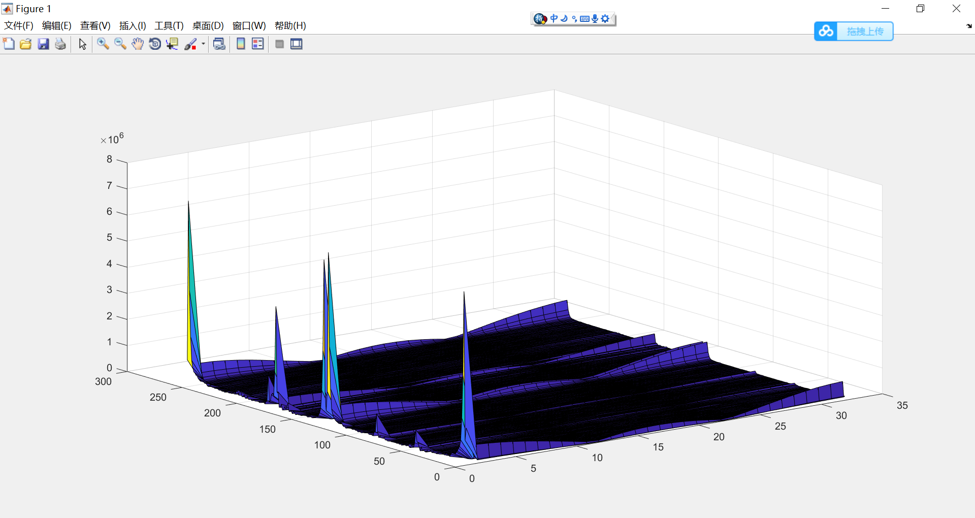
The 1DFFT/2DFFT result on TestCase006 is strange, it is very different with TestCase004, and there is direct component.
Thourgh TestCase004 and TestCase006 have different Profile and Chip params, but I expect the 1DFFT/2DFFT result should be similar.
Does the data layout in ADC data file captured is differnet for the two Cases.
1.2 scene, the chair is is about 2.00 meter in front of IWR6843ISK EVM

1.3 Two TestCases
TestCase004
use mmWave Studio to capture ADC binary,
below is 1DFFT/2DFFT result with matlab

TestCase006
use mmw demo and open LVDS with CLI "lvdsStreamCfg -1 0 1 0"
below is 1DFFT/2DFFT result with matlab
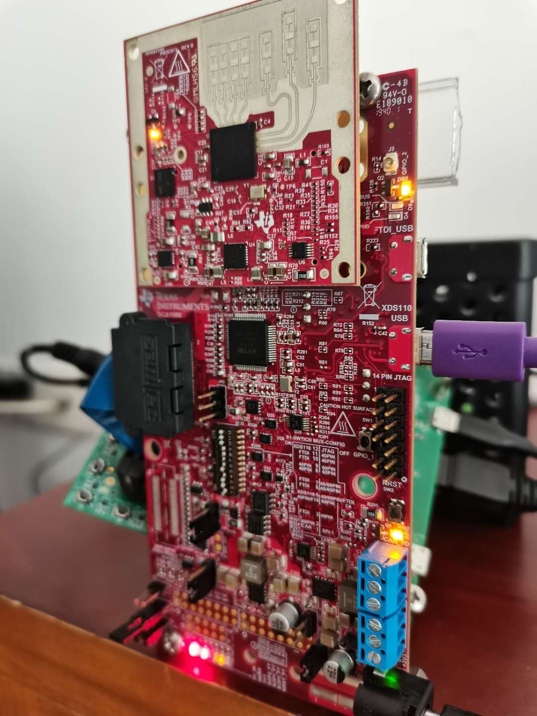
1.3 Environment:
IWR6843ISK EVM
DCA1000EVM
mmWave Studio
C:\ti\mmwave_studio_02_01_01_00\mmWaveStudio\mmw
C:\ti\mmwave_sdk_03_03_00_03\packages\ti\demo\xwr68xx\mmw
2.
TestCase004
2.1 I run a lua script inside mmWave studio, below is code:
--BSS and MSS firmware download
info = debug.getinfo(1,'S');
file_path = (info.source);
file_path = string.gsub(file_path, "@","");
file_path = string.gsub(file_path, "DataCaptureDemo_xWR.test.lua","");
fw_path = file_path.."..\\..\\rf_eval_firmware"
--Export bit operation file
bitopfile = file_path.."\\".."bitoperations.lua"
dofile(bitopfile)
--Read part ID
--This register address used to find part number for ES2 and ES3 devices
res, efusedevice = ar1.ReadRegister(0xFFFFE214, 0, 31)
res, efuseES1device = ar1.ReadRegister(0xFFFFE210, 0, 31)
efuseES2ES3Device = bit_and(efusedevice, 0x03FC0000)
efuseES2ES3Device = bit_rshift(efuseES2ES3Device, 18)
--if part number is zero then those are ES1 devices
if(efuseES2ES3Device == 0) then
if (bit_and(efuseES1device, 3) == 0) then
partId = 1243
elseif (bit_and(efuseES1device, 3) == 1) then
partId = 1443
else
partId = 1642
end
elseif(efuseES2ES3Device == 0xE0 and (bit_and(efuseES1device, 3) == 2)) then
partId = 6843
ar1.frequencyBandSelection("60G")
--if part number is non-zero then those are ES12 and ES3 devices
else
if(efuseES2ES3Device == 0x20 or efuseES2ES3Device == 0x21 or efuseES2ES3Device == 0x80) then
partId = 1243
elseif(efuseES2ES3Device == 0xA0 or efuseES2ES3Device == 0x40)then
partId = 1443
elseif(efuseES2ES3Device == 0x60 or efuseES2ES3Device == 0x61 or efuseES2ES3Device == 0x04 or efuseES2ES3Device == 0x62 or efuseES2ES3Device == 0x67) then
partId = 1642
elseif(efuseES2ES3Device == 0x66 or efuseES2ES3Device == 0x01 or efuseES2ES3Device == 0xC0 or efuseES2ES3Device == 0xC1) then
partId = 1642
elseif(efuseES2ES3Device == 0x70 or efuseES2ES3Device == 0x71 or efuseES2ES3Device == 0xD0 or efuseES2ES3Device == 0x05) then
partId = 1843
elseif(efuseES2ES3Device == 0xE0 or efuseES2ES3Device == 0xE1 or efuseES2ES3Device == 0xE2 or efuseES2ES3Device == 0xE3 or efuseES2ES3Device == 0xE4) then
partId = 6843
ar1.frequencyBandSelection("60G")
else
WriteToLog("Inavlid Device part number in ES2 and ES3 devices\n" ..partId)
end
end
--ES version
res, ESVersion = ar1.ReadRegister(0xFFFFE218, 0, 31)
ESVersion = bit_and(ESVersion, 15)
--ADC_Data file path
data_path = file_path.."..\\PostProc"
adc_data_path = data_path.."\\adc_data.TestCase004.bin"
-- Download Firmware
if(partId == 1642) then
BSS_FW = fw_path.."\\radarss\\xwr16xx_radarss.bin"
MSS_FW = fw_path.."\\masterss\\xwr16xx_masterss.bin"
elseif(partId == 1243) then
BSS_FW = fw_path.."\\radarss\\xwr12xx_xwr14xx_radarss.bin"
MSS_FW = fw_path.."\\masterss\\xwr12xx_xwr14xx_masterss.bin"
elseif(partId == 1443) then
BSS_FW = fw_path.."\\radarss\\xwr12xx_xwr14xx_radarss.bin"
MSS_FW = fw_path.."\\masterss\\xwr12xx_xwr14xx_masterss.bin"
elseif(partId == 1843) then
BSS_FW = fw_path.."\\radarss\\xwr18xx_radarss.bin"
MSS_FW = fw_path.."\\masterss\\xwr18xx_masterss.bin"
elseif(partId == 6843) then
BSS_FW = fw_path.."\\radarss\\xwr68xx_radarss.bin"
MSS_FW = fw_path.."\\masterss\\xwr68xx_masterss.bin"
else
WriteToLog("Invalid Device partId FW\n" ..partId)
WriteToLog("Invalid Device ESVersion\n" ..ESVersion)
end
-- Download BSS Firmware
if (ar1.DownloadBSSFw(BSS_FW) == 0) then
WriteToLog("BSS FW Download Success\n", "green")
else
WriteToLog("BSS FW Download failure\n", "red")
end
-- Download MSS Firmware
if (ar1.DownloadMSSFw(MSS_FW) == 0) then
WriteToLog("MSS FW Download Success\n", "green")
else
WriteToLog("MSS FW Download failure\n", "red")
end
-- SPI Connect
if (ar1.PowerOn(1, 1000, 0, 0) == 0) then
WriteToLog("Power On Success\n", "green")
else
WriteToLog("Power On failure\n", "red")
end
-- RF Power UP
if (ar1.RfEnable() == 0) then
WriteToLog("RF Enable Success\n", "green")
else
WriteToLog("RF Enable failure\n", "red")
end
if (ar1.ChanNAdcConfig(1, 1, 0, 1, 1, 1, 1, 2, 1, 0) == 0) then
WriteToLog("ChanNAdcConfig Success\n", "green")
else
WriteToLog("ChanNAdcConfig failure\n", "red")
end
if (partId == 1642) then
if (ar1.LPModConfig(0, 1) == 0) then
WriteToLog("LPModConfig Success\n", "green")
else
WriteToLog("LPModConfig failure\n", "red")
end
else
if (ar1.LPModConfig(0, 0) == 0) then
WriteToLog("Regualar mode Cfg Success\n", "green")
else
WriteToLog("Regualar mode Cfg failure\n", "red")
end
end
if (ar1.RfInit() == 0) then
WriteToLog("RfInit Success\n", "green")
else
WriteToLog("RfInit failure\n", "red")
end
RSTD.Sleep(1000)
if (ar1.DataPathConfig(1, 1, 0) == 0) then
WriteToLog("DataPathConfig Success\n", "green")
else
WriteToLog("DataPathConfig failure\n", "red")
end
if (ar1.LvdsClkConfig(1, 1) == 0) then
WriteToLog("LvdsClkConfig Success\n", "green")
else
WriteToLog("LvdsClkConfig failure\n", "red")
end
if((partId == 1642) or (partId == 1843) or (partId == 6843)) then
if (ar1.LVDSLaneConfig(0, 1, 1, 0, 0, 1, 0, 0) == 0) then
WriteToLog("LVDSLaneConfig Success\n", "green")
else
WriteToLog("LVDSLaneConfig failure\n", "red")
end
elseif ((partId == 1243) or (partId == 1443)) then
if (ar1.LVDSLaneConfig(0, 1, 1, 1, 1, 1, 0, 0) == 0) then
WriteToLog("LVDSLaneConfig Success\n", "green")
else
WriteToLog("LVDSLaneConfig failure\n", "red")
end
end
--if (ar1.SetTestSource(4, 3, 0, 0, 0, 0, -327, 0, -327, 327, 327, 327, -2.5, 327, 327, 0, 0, 0, 0, -327, 0, -327,
-- 327, 327, 327, -95, 0, 0, 0.5, 0, 1, 0, 1.5, 0, 0, 0, 0, 0, 0, 0) == 0) then
-- WriteToLog("Test Source Configuration Success\n", "green")
--else
-- WriteToLog("Test Source Configuration failure\n", "red")
--end
if((partId == 1642) or (partId == 1843)) then
if(ar1.ProfileConfig(0, 77, 100, 6, 60, 0, 0, 0, 0, 0, 0, 29.982, 0, 256, 5000, 0, 0, 30) == 0) then
WriteToLog("ProfileConfig Success\n", "green")
else
WriteToLog("ProfileConfig failure\n", "red")
end
elseif((partId == 1243) or (partId == 1443)) then
if(ar1.ProfileConfig(0, 77, 100, 6, 60, 0, 0, 0, 0, 0, 0, 29.982, 0, 256, 10000, 0, 0, 30) == 0) then
WriteToLog("ProfileConfig Success\n", "green")
else
WriteToLog("ProfileConfig failure\n", "red")
end
elseif(partId == 6843) then
if(ar1.ProfileConfig(0, 60.25, 100, 6, 60, 0, 0, 0, 0, 0, 0, 29.982, 0, 256, 10000, 0, 131072, 30) == 0) then
WriteToLog("ProfileConfig Success\n", "green")
else
WriteToLog("ProfileConfig failure\n", "red")
end
end
if (ar1.ChirpConfig(0, 0, 0, 0, 0, 0, 0, 1, 1, 0) == 0) then
WriteToLog("ChirpConfig Success\n", "green")
else
WriteToLog("ChirpConfig failure\n", "red")
end
-- if (ar1.EnableTestSource(1) == 0) then
-- WriteToLog("Enabling Test Source Success\n", "green")
-- else
-- WriteToLog("Enabling Test Source failure\n", "red")
-- end
if (ar1.FrameConfig(0, 0, 8, 128, 40, 0, 0, 1) == 0) then
WriteToLog("FrameConfig Success\n", "green")
else
WriteToLog("FrameConfig failure\n", "red")
end
-- select Device type
if (ar1.SelectCaptureDevice("DCA1000") == 0) then
WriteToLog("SelectCaptureDevice Success\n", "green")
else
WriteToLog("SelectCaptureDevice failure\n", "red")
end
--DATA CAPTURE CARD API
if (ar1.CaptureCardConfig_EthInit("192.168.33.30", "192.168.33.180", "12:34:56:78:90:12", 4096, 4098) == 0) then
WriteToLog("CaptureCardConfig_EthInit Success\n", "green")
else
WriteToLog("CaptureCardConfig_EthInit failure\n", "red")
end
WriteToLog("0001a\n", "green")
--AWR12xx or xWR14xx-1, xWR16xx or xWR18xx or xWR68xx- 2 (second parameter indicates the device type)
if ((partId == 1642) or (partId == 1843) or (partId == 6843)) then
if (ar1.CaptureCardConfig_Mode(1, 2, 1, 2, 3, 30) == 0) then
WriteToLog("CaptureCardConfig_Mode Success\n", "green")
else
WriteToLog("CaptureCardConfig_Mode failure\n", "red")
end
elseif ((partId == 1243) or (partId == 1443)) then
if (ar1.CaptureCardConfig_Mode(1, 1, 1, 2, 3, 30) == 0) then
WriteToLog("CaptureCardConfig_Mode Success\n", "green")
else
WriteToLog("CaptureCardConfig_Mode failure\n", "red")
end
end
if (ar1.CaptureCardConfig_PacketDelay(25) == 0) then
WriteToLog("CaptureCardConfig_PacketDelay Success\n", "green")
else
WriteToLog("CaptureCardConfig_PacketDelay failure\n", "red")
end
--Start Record ADC data
ar1.CaptureCardConfig_StartRecord(adc_data_path, 1)
RSTD.Sleep(1000)
--Trigger frame
ar1.StartFrame()
RSTD.Sleep(5000)
--Post process the Capture RAW ADC data
ar1.StartMatlabPostProc(adc_data_path)
WriteToLog("Please wait for a few seconds for matlab post processing .....!!!! \n", "green")
RSTD.Sleep(10000)
3.
TestCase006
3.1 I burn firmwave after compile mmw, and input CLI configure with profile_2d.cfg,
its content is below:
% Carrier frequency GHz 60
% Ramp Slope MHz/us 166
% Num ADC Samples 256
% ADC Sampling Rate Msps 12.5
% ADC Collection Time us 20.48
% Extra ramp time required (start time) us 3
% Chirp time (end time - start time) us 21
% Chirp duration (end time) us 24
% Sweep BW (useful) MHz 3399.68
% Total BW MHz 3984
% Max beat freq (80% of ADC sampling rate) MHz 10
% Max distance (80%) m 9.04
% Range resolution m 0.044
% Range resolution (meter per 1D-FFT bin) m/bin 0.044
%
% Inter-chirp duration us 7
% Number of chirp intervals in frame - 64
% Number of TX (TDM MIMO) 2
% Number of Tx elevation antennas 0
% Number of RX channels - 4
% Max umambiguous relative velocity kmph 72.58
% mileph 45.36
% Max extended relative velocity kmph 145.16
% mileph 90.73
% Frame time (total) ms 1.984
% Frame time (active) ms 1.536
% Range FFT size - 256
% Doppler FFT size - 32
% Radar data memory required KB 272
% Velocity resolution m/s 1.26
% Velocity resolution (m/s per 2D-FFT bin) m/s/bin 1.26
% Velocity Maximum m/s 20.16
% Extended Maximum Velocity m/s 40.32
% Maximum sweep accorss range bins range bin 0.91
%
sensorStop
flushCfg
dfeDataOutputMode 1
channelCfg 15 5 0
adcCfg 2 1
adcbufCfg -1 0 1 1 1
lowPower 0 0
profileCfg 0 60 7 3 24 0 0 166 1 256 12500 0 0 30
chirpCfg 0 0 0 0 0 0 0 1
chirpCfg 1 1 0 0 0 0 0 4
frameCfg 0 1 32 0 100 1 0
guiMonitor -1 1 1 1 0 0 1
cfarCfg -1 0 2 8 4 3 0 15.0 0
cfarCfg -1 1 0 4 2 3 1 15.0 0
multiObjBeamForming -1 1 0.5
calibDcRangeSig -1 0 -5 8 256
clutterRemoval -1 0
compRangeBiasAndRxChanPhase 0.0 1 0 1 0 1 0 1 0 1 0 1 0 1 0 1 0 1 0 1 0 1 0 1 0
measureRangeBiasAndRxChanPhase 0 1. 0.2
aoaFovCfg -1 -90 90 -90 90
cfarFovCfg -1 0 0.25 9.0
cfarFovCfg -1 1 -20.16 20.16
extendedMaxVelocity -1 0
CQRxSatMonitor 0 3 4 63 0
CQSigImgMonitor 0 127 4
analogMonitor 0 0
lvdsStreamCfg -1 0 1 0
bpmCfg -1 0 0 0
sensorStart
3.2 I use CLI below for capture ADC data,
DCA1000EVM_CLI_Control.exe fpga datacard_config.json
DCA1000EVM_CLI_Control.exe record datacard_config.json
DCA1000EVM_CLI_Control.exe start_record datacard_config.json
DCA1000EVM_CLI_Control.exe stop_record datacard_config.json
datacard_config.json:
{
"DCA1000Config": {
"dataLoggingMode": "raw",
"dataTransferMode": "LVDSCapture",
"dataCaptureMode": "ethernetStream",
"lvdsMode": 2,
"dataFormatMode": 3,
"packetDelay_us": 10,
"ethernetConfig": {
"DCA1000IPAddress": "192.168.33.180",
"DCA1000ConfigPort": 4096,
"DCA1000DataPort": 4098
},
"ethernetConfigUpdate": {
"systemIPAddress": "192.168.33.30",
"DCA1000IPAddress": "192.168.33.180",
"DCA1000MACAddress": "12.34.56.78.90.12",
"DCA1000ConfigPort": 4096,
"DCA1000DataPort": 4098
},
"captureConfig": {
"fileBasePath": "C:\\ti\\mmwave_studio_02_01_01_00\\mmWaveStudio\\PostProc",
"filePrefix": "adc_data.TestCase006",
"maxRecFileSize_MB": 1024,
"sequenceNumberEnable": 1,
"captureStopMode": "bytes",
"bytesToCapture": 4194304,
"durationToCapture_ms": 1000,
"framesToCapture": 5
},
"dataFormatConfig": {
"MSBToggle": 0,
"reorderEnable": 1,
"laneFmtMap": 0,
"dataPortConfig": [
{
"portIdx": 0,
"dataType": "complex"
},
{
"portIdx": 1,
"dataType": "complex"
},
{
"portIdx": 2,
"dataType": "complex"
},
{
"portIdx": 3,
"dataType": "complex"
},
{
"portIdx": 4,
"dataType": "complex"
}
]
}
}
}
4. The matlab is as below
4.1 adc_binParase.m:
%% Parasing the adc_data.bin from DCA1000 with ti iwr6843 evm demo
fname ='adc_data.TestCase006_Raw_0.bin'; % the source data
fid = fopen(fname,'rb');
% calculating the size of file with byte
% fseek(fid,0,'eof');
% fsize = ftell(fid);
% n_samples:ADC sample points with chirp; n_chirps: the number of chirp
% in one frame;n_Rx: the number of receive antennas;n_Tx:the number of
% transmit antennas, for multi tx antennas tranmit simultaneously,the
% n_Tx = 1
n_samples = 256;
n_chirps = 32;
n_Rx = 4;
n_Tx = 2;
sdata = fread(fid,n_samples*n_chirps*n_Rx*n_Tx*2,'int16');
%split
fileSize = size(sdata, 1);
lvds_data = zeros(1, fileSize/2);
count = 1;
for i=1:4:fileSize-5
lvds_data(1,count) = sdata(i) + 1i*sdata(i+2);
lvds_data(1,count+1) = sdata(i+1)+1i*sdata(i+3); %IQ
count = count + 2;
end
n_RX = n_Rx*n_Tx;
lvds_data = reshape(lvds_data, n_samples*n_RX, n_chirps);
lvds_data = lvds_data.';
cdata = zeros(n_RX,n_chirps*n_samples);
for row = 1:n_RX
for i = 1: n_chirps
cdata(row,(i-1)*n_samples+1:i*n_samples) = lvds_data(i,(row-1)*n_samples+1:row*n_samples);
end
end
fclose(fid);
RX1data = reshape(cdata(1,:),n_samples,n_chirps); %RX1
RX2data = reshape(cdata(2,:),n_samples,n_chirps); %RX2
RX3data = reshape(cdata(3,:),n_samples,n_chirps); %RX3
RX4data = reshape(cdata(4,:),n_samples,n_chirps); %RX4
4.2 RSP_SPT.m
%% 2D-FFT
clear
close all
run( 'adc_binParase.m' );
ODFFTReal =zeros(n_samples,n_chirps);
ODFFTImage =zeros(n_samples,n_chirps);
ODFFT = complex(ODFFTReal,ODFFTImage);
for j = 1:1:n_chirps
ODFFT(:,j) = fft(RX1data(:,j));
end
for i = 1:1:n_samples
ODFFT(i,:) = fft(ODFFT(i,:));
end
surf(1:1:n_chirps,1:1:n_samples,abs(ODFFT(:,:)));
TEST = 1;
4.3 variabe values for two case
TestCase004
n_samples = 256;
n_chirps = 128;
n_Rx = 4;
n_Tx = 1;
TestCase006:
n_samples = 256;
n_chirps = 32;
n_Rx = 4;
n_Tx = 2;
