This thread has been locked.

If you have a related question, please click the "Ask a related question" button in the top right corner. The newly created question will be automatically linked to this question.

DCA1000EVM: Cannot connect RS232 to mmWave Studio 2.1.1.0

Part Number: DCA1000EVM
Other Parts Discussed in Thread: IWR6843ISK-ODS, MMWAVEICBOOST, , UNIFLASH, IWR6843ISK

HI all,

I am attempting to run one of the demos through the mmWave studio 2.1.1.0 software using the following equipment:

IWR6843ISK-ODS

MMWAVEICBOOST

DCA1000EVM

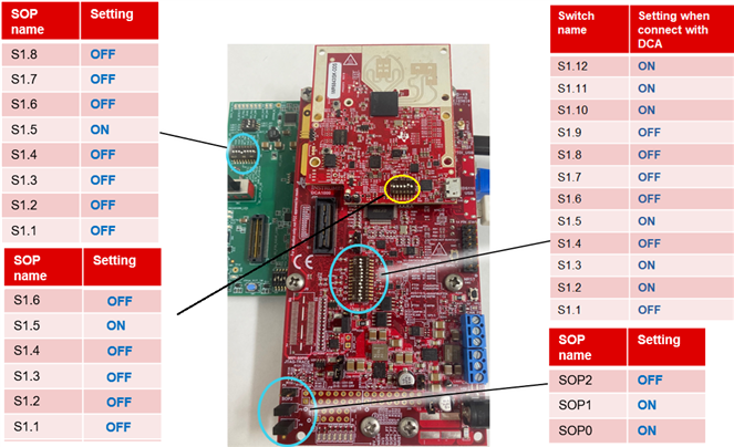
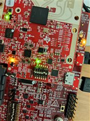
I believe I have connected everything up correctly, I have the jumpers across SOP 0 and SOP 1 with SOP 2 open on the mmwaveicboost board, and the dip switches s1.1-12 are set to the DCA mode.

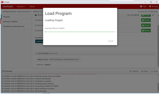
However, I get the following error and the RS232 connectivity status is always set to disconnected:

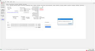
For background here is a screenshot of my USB ports:

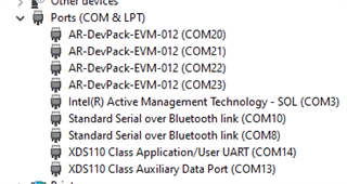
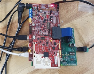
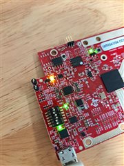
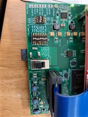
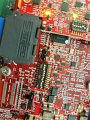
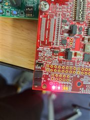
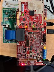
And photos of my setup:

Appreciate any help you can provide.

  • Hello,

    Your device manager is correct, your switch orientation is correct on the ICBOOST and mmWave Sensor. The DCA switches however do not match what is seen in the DCA1000 User Guide in the Radar Toolbox on TI Resource Explorer. 

    https://dev.ti.com/tirex/explore/node?a=1AslXXD__1.00.01.07&node=A__AGTrhNYW8jE6cMxbovlfaA__radar_toolbox__1AslXXD__1.00.01.07

    Also in your example I see one USB cable coming from the ICBOOST, which is correct, but do you have a second one connected from the RADAR_FTDI port of the DCA1000 to the computer?

    Best Regards,

    Pedrhom Nafisi

  • Hi Pedrhom
    Apologies for not getting back to you sooner, public holidays in Australia meant I only returned to work yesterday.
    I've fixed the SOP switches on the DCA1000EVM board, and still run into the same issue.
    Cables are connected correctly at the RADAR_FTDI port on DCA1000EVM and the XDS110 port on the ICBOOST board.
    See picture below:

  • Hello,

    Your switch orientation seems correct now. What is your power supply rated to? DCA1000 requires 5V 3A to operate properly. You also are to provide power from either the DCA1000 side or the ICBOOST side, and then flip the switch depending on which side you connected power to. In your picture I see two power supplies connected. Another thing you can potentially try is clearing the flash on the mmWave Sensor via Uniflash to ensure a clean state of a starting point

    Best Regards,

    Pedrhom

  • Hi Pedrhom

    I originally was using a 5V 1A power supply (both ends). I've tried with both all power combinations: DCA switch set to DC_JACK_5V_IN, powered to DCA (this results in no power to the radar or mmwaveicboost). 

    Also tried with DCA switch set RADAR_5V_IN (this results in power to all three boards, same result if both ends are powered).

    Now I've changed it to use our lab's variable power supply, set to 5V and current set to max 3A. However, when plugged in, DCA1000EVM is only drawing between 0.3 and 0.7A, and still no luck successfully connecting to RS232.

    Additionally, I can't flash the memory of the radar with Uniflash as the software cannot connect to the serial port (for what I assume are similar reasons).

    Kind regards,

    Ben

  • Can you try clearing the flash buy removing the ICBOOST and DCA1000, and connecting just the sensor? See if you can communicate with it serially in order to isolate each device

    Best Regards,

    Pedrhom Nafisi

  • HI Pedrhom,

    When I connect the IWR6843ISK on its own and connect through Uniflash, I get stuck here:

    It doesn't seem to be able to open the COM port.
    Note if I select any other port, then it will stop and tell me it failed to connect, but when I select the correct port it simply sits in this state for hwat seems like forever.

  • Hello,

    When you connected ISK on its own, did you switch the pin configuration to the proper flashing mode for standalone ISK? What you are seeing is generally what happens when the sensor is not in the proper mode to be flashed.

    https://dev.ti.com/tirex/explore/node?a=1AslXXD__1.00.01.07&node=A__ACzleIuZ4g1GuBmtlq-cGg__radar_toolbox__1AslXXD__1.00.01.07

    Best Regards,

    Pedrhom

  • Hi Pedrhom,
    Apologies for the slow reply.
    Yes I did change the switches to flashing mode. Tried again today, (see image below), but the same error occurs.

  • Hi again, I've tested on 3 different PCs to see if it was an issue with ports being used, or permissions including with elevated admin privileges, but still no luck. It is completely unable to communicate with the serial port.

  • Hello,

    I'm sorry to hear about the amount of issues you have been facing. It seems that the issue has been isolated to communication with the EVM. If you are able to see the two COM ports representing the mmWave Sensor (which it seems you are) and cannot flash or erase flash to the Application/User UART port, and as it looks your switches are in the right position, and you have tried different cables and computers, then it is possible there is a defection with your EVM. Please create a customer service ticket and you can have them reference this thread or me.

    Best Regards,

    Pedrhom